Premier Elite Series Installation Manual Installation
INS176-15 25
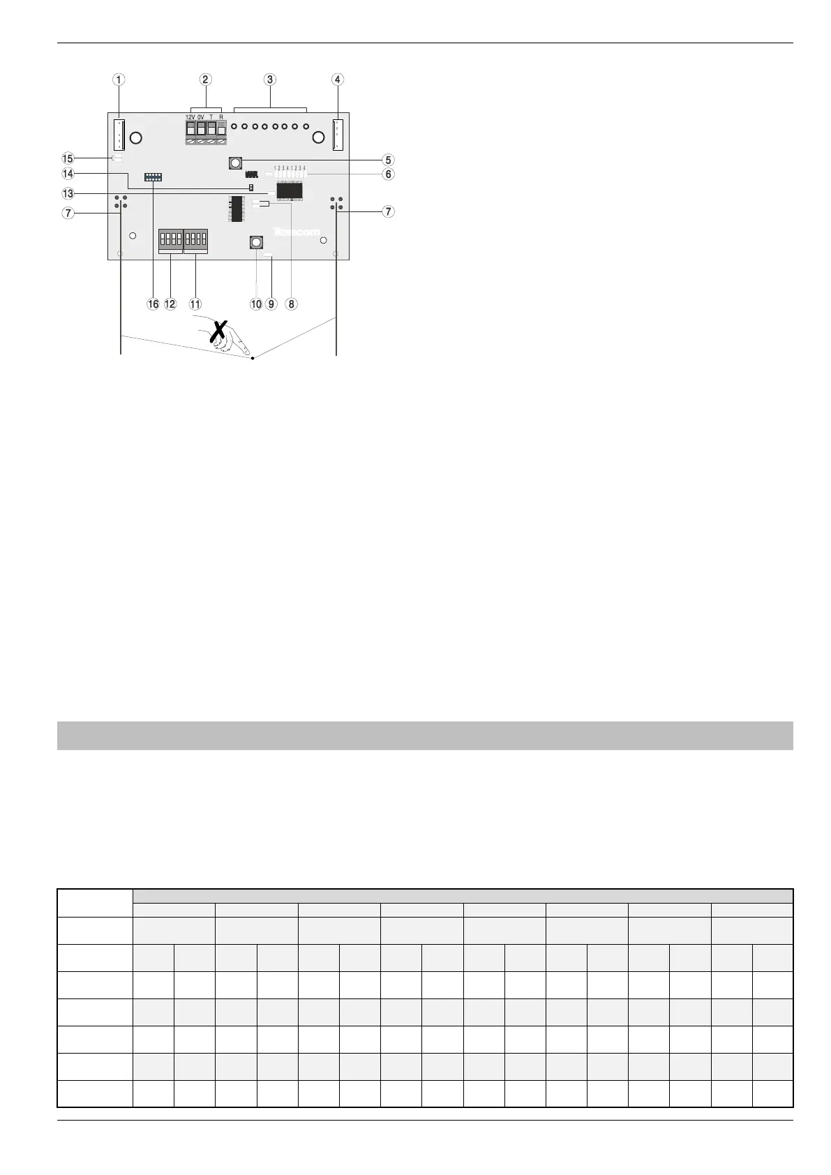
PCB Layout
1: Engineers Keypad Connection
An engineer’s keypad (Premier/Elite LCD keypad and interface lead)
can be temporarily plugged onto this connector to allow system
programming and testing. (Functions dependent on Panel firmware
version) Set the keypad address switches to all on.
2: Network Connection
The + and – terminals provide power whilst the T and R terminals are
transmit and receive data.
3: For Future Use
4: Comm. Port Connection
Serial communications port for connecting the 8 XP-W & 32XP-W to a
PC via PC Com/USB Com or Com IP for use with Ricochet Monitor
Software.
5: Lid Tamper
When open puts the system into commission mode and digitally
attenuates the receiver signal by 15Db.
6: Programming LED’s
Allows programming of devices directly to the receiver, in
conjunction with the learn switch. Also able to indicate device
diagnostics from V3 onwards.
7: Antenna
RF Antenna.
Premier 32XP-W = 2 x Antenna
Premier 8XP-W = 1 x Antenna
8: Network LED's
Green LED = Data received by the expander from the panel Red LED
= Data transmitted by the expander to the panel. (The flash rate
depends on the mode and RF activity)
9: Heartbeat LED
Flashes steadily to indicate that the receiver is functioning correctly. If
the light is ON or OFF all the time, then there could be a hardware
problem.
10: Learn Switch
To be used with programming LED’s to learn devices directly to the
receiver.
11: Options Switch
Use to select the receiver functionality depending on panel firmware.
Switch 1 ON =firmware dependant, please see the relevant
programming section.
Switch 2 ON = Legacy Mode
OFF = Ricochet
Switch 3 ON = Impaq Contact-W Wired Input 2 will report as Tamper
(default)
OFF = input 2 will report as an Alarm.
Switch 4 Walk test
12: Address Switch
Used to assign the address of the receiver on the premier network
13: RF LED
Flashes when transmitting or receiving RF data
14: Tamper Disable
Disables the lid and rear tamper
15: Engineer’s Keypad LED's
Red LED flashes constantly, the flash rate increases when data is
being transmitted.
16: Flash Programming Port
Variant dependent, for flashing the expander with updated firmware.
Ricochet V2 & V3 Expander Addressing
Introduction
The address range and switch position will depend on which combination of expanders are being used. Each 32XP-W takes up 4 address slots on
the control panel network, however the network slots are virtual until devices are assigned to available zones. It is possible that if a 32XP-W is being
used at Address 1, but only 16 devices have been used, Address 3 & 4 are available for hardwired 8XP's or 8XP-W's.
Please see some examples of mixing different types of Expanders on various Elite panels and the addressing requirements.
Example 1 Totally wireless system(s)

 Loading...