Installation Premier Elite Series Installation Manual
42 INS176-15
AV Module
Before connecting the AV Module, isolate ALL power from the control
panel (AC mains and battery), do not continue if there is still power
present on the control panel.
To install the AV Module onto the control panel:
• Connect one end of the patch lead on to the Expansion Port of
the AV Module
• Connect one other end of the patch lead on to the Expansion
Port of the control panel
Programming the AV Module
• Program the Expansion Port for AV Module operation (see page
101 for details)
• Refer to the AV Module installation guide for full programming
details.
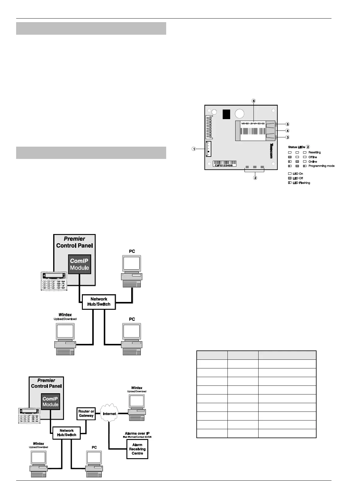
ComIP Module
The ComIP module allows the Premier Elite control panels to be
connected to either a Local Area Network (LAN) or Wide Area
Network (WAN). The internet is considered as a WAN. Once the
control panel is connected to a network the following features can be
achieved:
• Upload/Download via Wintex UDL
• Signal alarms to an Alarm Receiving Centre
• High security polling by Alarm Receiving Centre
Typical LAN configuration
Typical WAN configuration
Installation
General
The installation of the ComIP module requires a basic understanding
of networking and TCP/IP protocol. If you are not familiar with these
concepts, you may require assistance from an IT professional before
attempting to install the module.
The ComIP module is designed to be fitted inside the control panel
and is powered via the harness connection. A suitable network cable
should be fed into the control panel to allow connection the module.
PCB Layout
5-way harness connection to control panel
ComIP Status LEDs
Network status LED (Left)
RJ45 network Connection
Network status LED (Right)
MAC address
Installation
1. Select “Engineers” mode on the control panel then remove
the control panel lid.
2. Choose a suitable location for the module. Remember to
allow enough space to plug in the network cable and
connect the harness lead (supplied).
3. Fit the 4 self-adhesive feet supplied to the four mounting
holes. Remove the self-adhesive backing paper and secure
to the base of the control panel.
4. Connect the 5-way end of the harness to the 5-way
connector on the module.
5. Connect the other end onto a control panel communication
port.
6. Connect the network cable to the RJ45 connection on the
module. The network status LED’s indicate the following:

 Loading...