Installation Premier Elite Series Installation Manual
26 INS176-15
Example 2 Premier Elite 168™, + 32XP-W, 8XP-W's & 8XP's mix
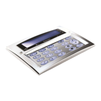
8XE Zone Expander (24 Only)
The 8XE Zone Expander has:
• 8 fully programmable zones
• Aux 12V Output
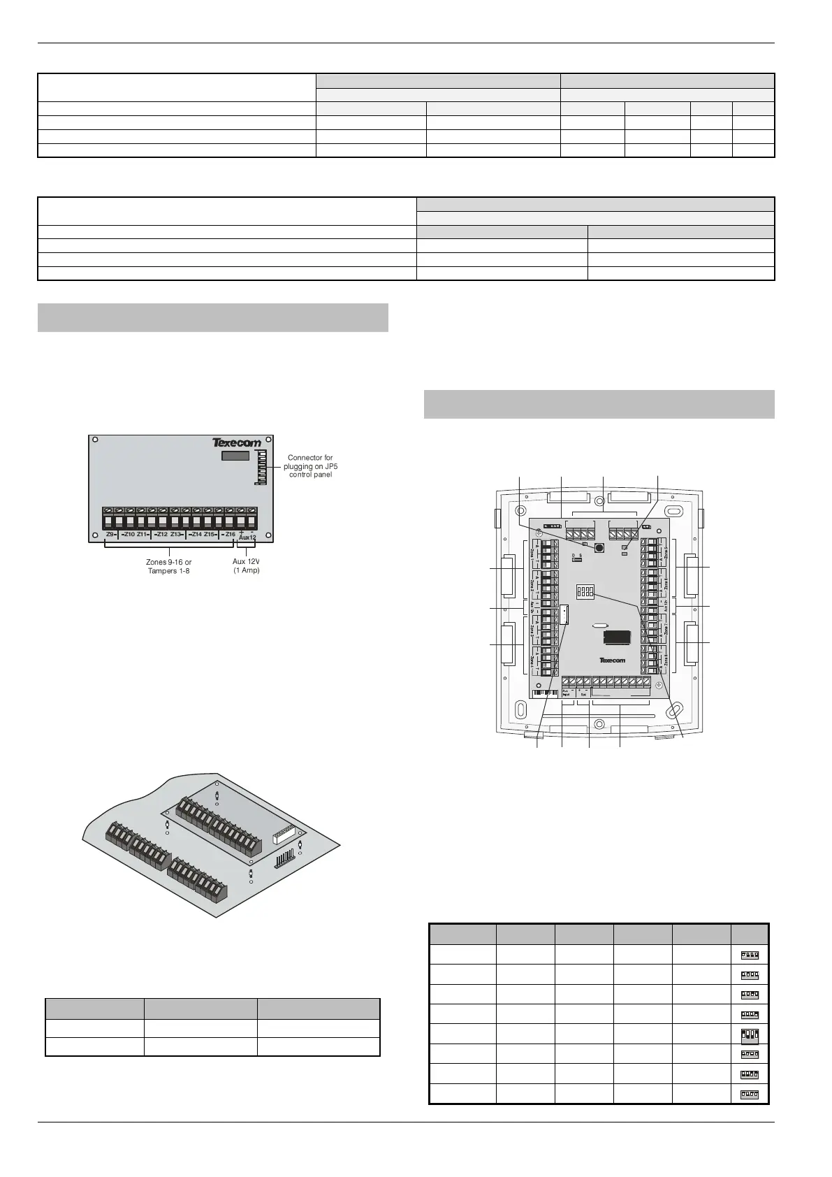
Expander Layout
Connecting Expanders
The 8XE local zone expander plugs directly on to the terminals located
on the right hand side of the control panel (see below for details). To
install the local zone expander proceed as follows:
1. Ensure that all power is removed from the control panel (mains and
battery) before attempting to fit the expander.
2. Push the four support pillars (supplied) into the four locating
holes on the control panel PCB.
3. Align the local expander connector with the 8 way plug (JP5) on
the control panel. Push expander into place, ensuring that all
four pillars clip into the four locating holes on the local
expander.
Zone Numbering
The table below shows the zone allocation when the expanders are
installed:
Expander Zones
The expander has eight programmable zones (see page 32 for wiring
details). Each zone is also fully programmable (see page 54 for
programming details).
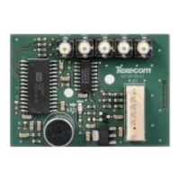
8XP Zone Expander
Expander Layout
Connecting Expanders
Expanders are connected to the network terminals located at the
bottom of the control panel (see pages 20 & 22 for details).
Expander Addressing
Each Expander must be assigned a different address using the DIL
switches located in the centre of the PCB. The table below shows the
expander addressing:

 Loading...