Installation Premier Elite Series Installation Manual
28 INS176-15
Expander Outputs
The zone expander has eight programmable outputs, which can be
used to drive auxiliary devices such as LED’s, sounders or relays etc.
Wire as per Panel Outputs shown on page 35 (see page 83 for
details). The electrical characteristics for the outputs are shown
below:
Expander Speaker Output
The expander has an output that can be used for driving up to one 16
or two 8 loudspeakers (see page 34 for details).
Expander Com Port
The Com Port can be used to connect a PSU200 or a monitored
power supply.
Expander Lid Tamper
The lid tamper of each expander can be disabled if required by fitting
a jumper link across the centre and right hand pins of the ‘Enable
Tamper’ pins (JP2) leaving the left hand pin free. These pins are
located to the left of the address DIL switch just beneath the fuse.
iProx Module
iProx Layout
Options
1
ON
2 3 4
1
ON
2 3 4
Address
RTE
N/C N/O Com
+
T R
Spk +
D 0
D1
C1
L1-
C2
L2- L+
Tamper
Ext Coil
Remote LED’s
Relay 1
Ext Int Ext Int
Internal Sounder
Off
On
Connection
The iProx Module is connected to the network terminals located at
the bottom of the control panel (see pages 20 & 22 for details).
Addressing
The iProx Module is addressed as a keypad and will occupy a
keypad slot on the network. The unit must have a unique address,
which must not conflict with keypad or any other iProx Module on
the same network
The following table shows the addressing:
Never set two modules on the same network to the same
address.
*88/168 & 640 only
Refer to the iProx Module manual for programming and operating
instructions.
60iXD Zone Expander
The 60iXD expander provides the following facilities:
• Two iD loops each supporting up to 30 biscuits
• Fused 12V output for powering detectors
• Engineer’s keypad port for local iD diagnostics
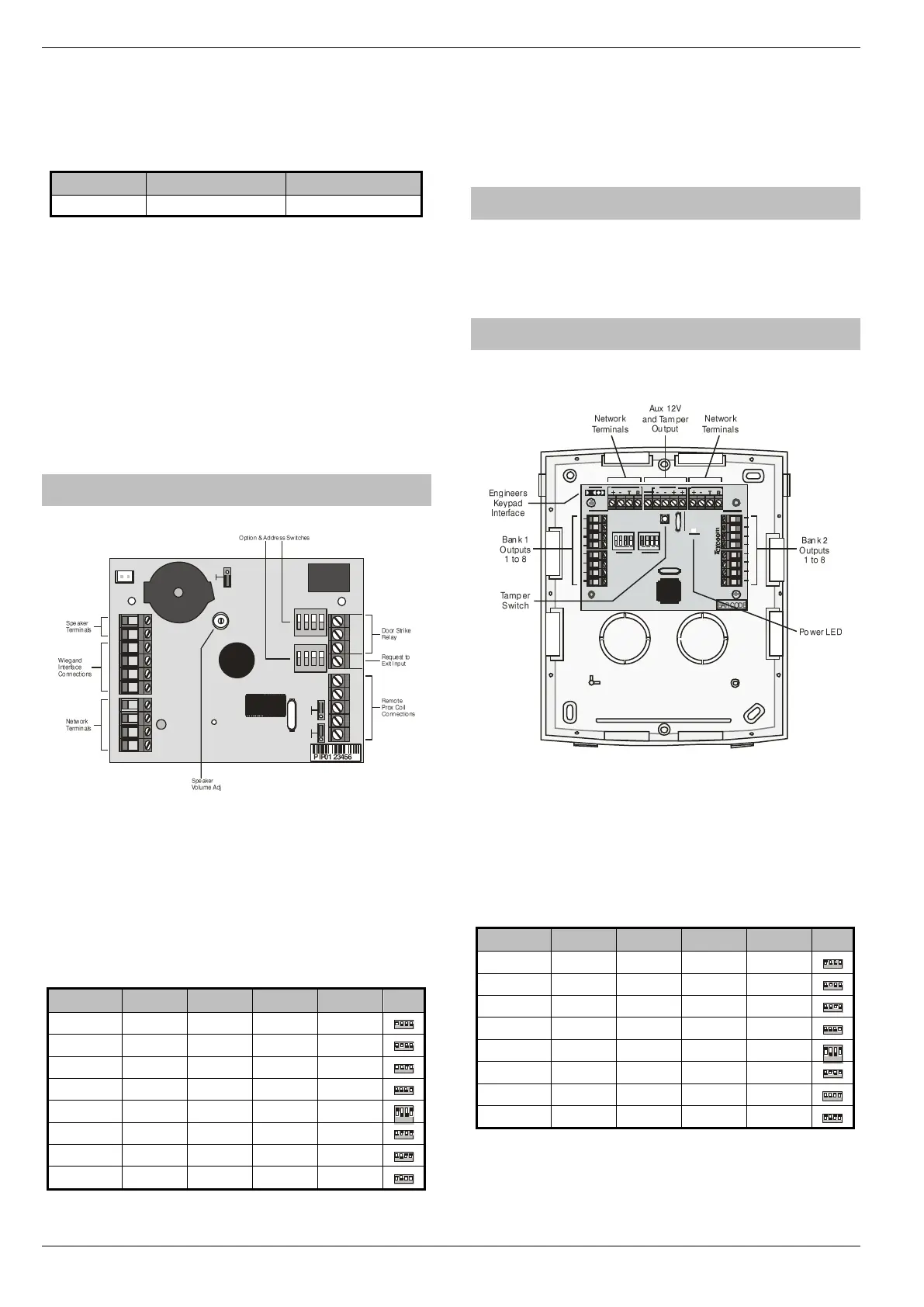
OP16 Output Expander
Output Module Layout
Connecting Output Modules
Output modules are connected to the network terminals located at
the bottom left hand corner of the control panel (see pages 20 & 22
for details).
Output Module Addressing
Each output module must be assigned a different address using the
DIL switches located in the centre of the PCB.
The table below shows the expander addressing:
* 88 and 168 only
** 168 only

 Loading...