Premier Elite Series Installation Manual Installation
INS176-15 21
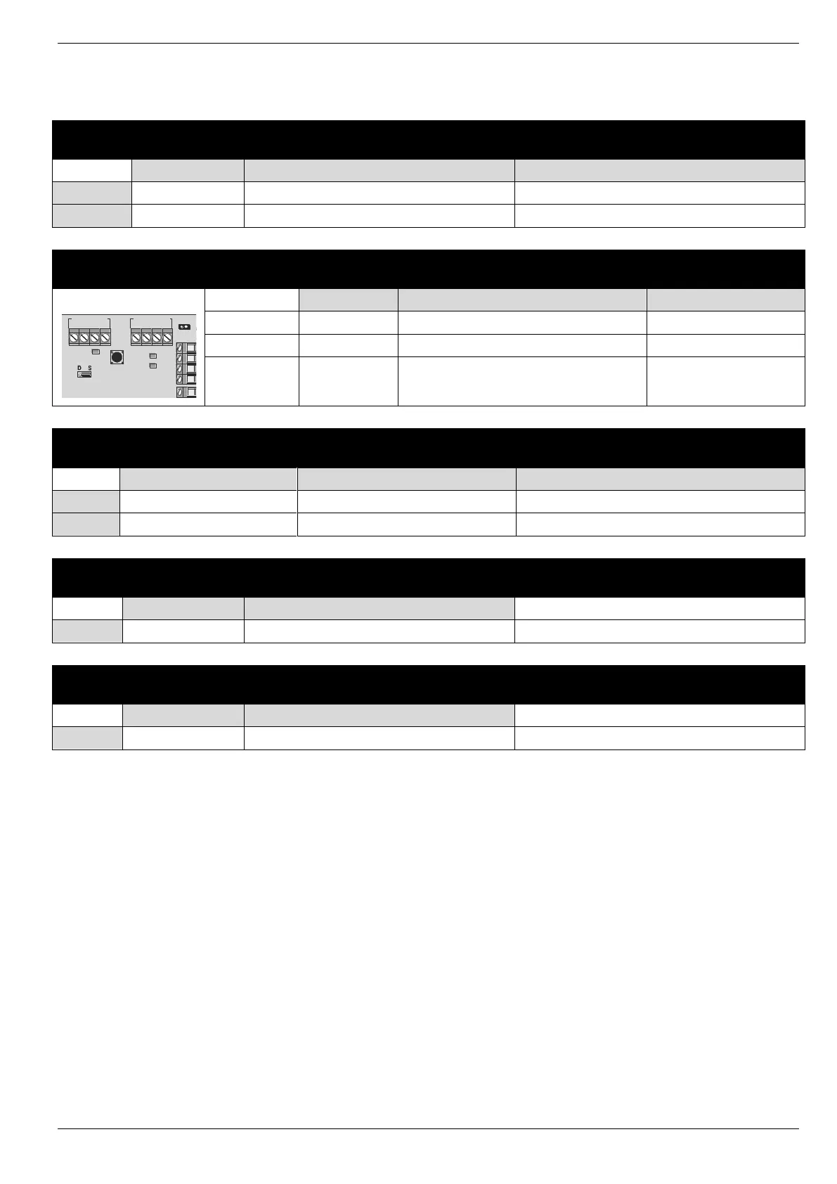
LED Network Diagnostics
Each network has two LED’s to indicate data flow. The red LED indicates data flowing out of the ‘T’ terminal and the green LED indicates data
flowing into the ‘R’ terminal. The table below shows each LED status and its meaning:
Normal operation when device is connected
No devices connected or short to 12v
Data pulses from devices on Network Out
Network Out not Connected
Flashes address number when in Engineering
/ all expanders flash as one until first
connected
No connection on 'T' wire
No connection on 'T' wire / Incorrectly addressed
No connection on 'T' wire
No connection on 'T' wire
The LED’s are provided as an aid for fault finding and therefore should not be completely relied upon to indicate that there is a fault.
1 2 3
OUTPUTS
4 5 6 7 8
NETWORK IN
+
-
T R +
-
T R
NETWORK OUT
Remote
Power
1
ON
2 3 4
PSU
YPE0123456
Tamper
Disable
A
B
C

 Loading...