Home
TOHATSU
Outboard Motor
BFT75A
Page 271 (Component Location)
TOHATSU BFT75A - Component Location
609 pages
Manual
Save Page as PDF
To Next Page
To Next Page
To Previous Page
To Previous Page
Loading...
7-4
dummyhe
ad
dummyhe
ad
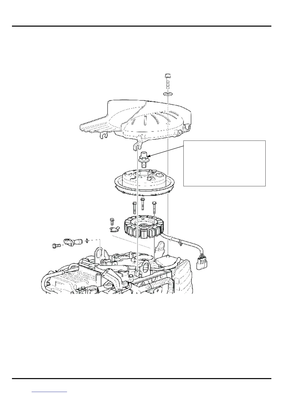
CHARGING SYSTEM
COMPONENT LOCATION
Tighten the bolt
in 3 steps:
1. Torque to 187
N·m (19.1 kgf·m,
138 lbf·ft) to sea
t the alternator rotor,
and then loosen
the bolt.
2. Torque to 37
N·m (3.8 kgf·m,
27 lbf·ft).
3. Tighten an
additional 90°.
270
272
Table of Contents
Main Page
Table of Contents
4
Specifications
5
Lower Unit
15
Service Information
20
Maintenance
21
Standard Torque Values
26
Special Tools
31
3. Maintenance
78
Maintenance Schedule
79
Operating Hour Notification System
80
Change
81
Engine Oil Level Check/Oil
81
Engine Oil Filter Change
82
Gear Case Oil Change
83
Throttle Control Cable/Throttle Link Check/Adjustment
86
Adjustment
89
Valve Clearance Check
89
Spark Plug Check/Replacement
92
Anode Metal Check (Outer Side)
94
Pin Check
94
Anode Metal Check (Inner Side)
96
Idle Speed Check/Adjustment
97
Lubrication
99
Fuel Strainer (Low Pressure Side) Inspection/Cleaning
102
Water Separator Check
102
Fuel Filter (High Pressure Side) Inspection/Replacement
105
Fuel Tank/Filter Cleaning
106
Fuel Line Check/Replacement
107
Crankcase Breather Check
108
Emergency Stop Switch Check
108
Nuts, Bolts, Fasteners
108
Water Pump Check
108
Adjustment
109
Power Trim/Tilt Check
109
Shift Control Cable Check
109
4. Troubleshooting
114
Alert System/Warning System Troubleshooting
115
Before Troubleshooting
115
Engine Troubleshooting
115
Frame Troubleshooting
136
Troubleshooting
136
5. Fuel System
142
Fuel System
142
Service Precautions
143
Engine Cover
146
Piping Connections
148
Circuit Diagram
149
System Location
151
Ecm Terminal Arrangement
152
Dtc Troubleshooting
154
Mil Troubleshooting
184
Solenoid Valve
201
Fuel Pressure Relieving
207
Fuel Pump (Low Pressure Side) Removal/Installation
208
Silencer Case Removal
208
Installation
208
Intake Manifold Removal
210
Installation
210
Fuel Injectors Removal
214
Installation
214
Fuel Pump (High Pressure Side)/Vapor Separator Removal/Installation
217
Map Sensor Removal/Installation
222
Iat Sensor Removal/Installation
222
Iac Valve Removal/Installation
223
Ho2S Removal/Installation
223
Vtec Solenoid Valve Removal/ Installation (Bf90D/Bf100A Only)
223
Ckp Sensor Removal/Installation
224
Cmp Sensor Removal/Installation
224
Eop Sensor Removal/Installation
225
Knock Sensor Removal/Installation
225
Ebt Sensor Removal/Installation
225
Ect Sensor 2 Removal/Installation
226
Ect Sensor 3 Removal/Installation
226
Air Vent Strainer/Check Valve Removal/Installation
227
Water Separator Removal
228
Installation
228
Water Separator Disassembly
230
Assembly
231
Silencer Case Disassembly
231
Fuel Pump (High Pressure Side)/Vapor Separator Disassembly/Assembly
232
Fuel Tank/Fuel Tank Tube Disassembly/Assembly
237
Fuel Pressure Measurement
238
Fuel Pressure Regulator
239
Inspection
239
Fuel Pump (Low Pressure Side)
240
Inspection
240
Fuel Pump (High Pressure Side)
240
Vapor Separator Inspection
243
Fuel Injector Inspection
244
Throttle Body Inspection
246
Ebt Sensor/Ect Sensor 2/3
247
Inspection
247
Water Level Sensor Inspection
247
Vtec Solenoid Valve Inspection (Bf90D/Bf100A Only)
248
Iac Valve Inspection
248
Iat Sensor Inspection
248
Ho2S Inspection
249
6. Engine Cover
250
Component Location
251
Engine Cover Removal
252
Installation
252
Front Separate Cover Removal
253
Installation
253
Installation
256
Installation
261
Under Cover Front Bracket Removal/Installation
261
Under Cover Front Bracket Disassembly/Assembly
266
Assembly
267
Under Cover Rear Bracket Disassembly/Assembly
267
7. Charging System
268
Charging System
269
System Diagram
269
System Location
269
Troubleshooting
270
Component Location
271
Alternator Cover
272
Alternator Removal
273
Installation
273
Alternator Inspection
280
Regulator/Rectifier Inspection
280
Ignition System
282
9. Starting System
286
Starting System
287
System Diagram
287
System Location
287
Troubleshooting
288
Installation
290
Starter Motor Removal
290
Flywheel Removal/Installation
293
Starter Motor Disassembly
295
Assembly
300
Starter Motor Inspection
304
Flywheel Inspection
307
Neutral Switch Inspection
307
10. Other Electrical
308
Other Electrical
308
System Location
309
Regulator/Rectifier/Fuse Box/70 Afuse Box Removal/Installation
311
Starter Cable/Fuse Cable Removal/Installation
313
Power Tilt Relay/Relay Bracket Removal/Installation
318
Pgm-Fi/Main Relay Inspection
320
Fuse Box Inspection
321
70 A Fuse Box/Fuse Inspection
321
Power Tilt Relay Inspection
322
Power Trim/Tilt Switch Inspection (Outboard Motor Side)
323
Trim Angle Sensor Inspection
323
11. Cooling System
324
Cooling System
324
Component Location
325
Water Line Description
326
Thermostat/Water Jacket Cover Removal/Installation
327
Water Pump Removal
329
Installation
329
Installation
332
Thermostat Inspection
335
12. Lubrication System
336
Lubrication System
336
Component Location
337
Lubrication System Diagram
338
Starting Procedure after Installing Major Assemblies
339
Engine Removal/Installation
339
Oil Case Removal/Installation
340
Oil Pump Removal/Installation
342
Cylinder Head
342
Oil Pump Disassembly/Assembly
343
Oil Pressure Check
345
Oil Pump Inspection
345
Engine Installation
355
14. Cylinder Head
360
Component Location
361
Chain Case/Cam Chain Removal
363
Installation
363
Cylinder Block
371
Cylinder Head Cover Removal
374
Installation
374
Cylinder Head Removal
378
Installation
378
Cylinder Head Assembly
381
Disassembly
381
Assembly
385
Cylinder Compression Test
391
Cylinder Head Inspection
391
Valve Guide Replacement
399
Valve Seat Reconditioning
400
Cylinder Block
402
16. Gear Case
430
Gear Case
430
Component Location
431
Installation
432
Anode Metal/Water Screen Removal/Installation
433
Gear Case/Extension Separator
434
(Xrt Type Only) Removal
434
Installation
436
Extension Case/Lower Rubber Removal/Installation
438
Mount
438
Installation
440
Propeller Shaft Holder Removal/Installation
447
Shift Slider/Propeller Shaft Removal/Installation
448
Vertical Shaft/Forward Bevel Gear Removal/Installation
454
Propeller Shaft Holder Disassembly/Assembly
459
Vertical Shaft Disassembly
462
Assembly
462
Shim Selection
465
Backlash Inspection
470
Propeller Shaft Inspection
473
Vertical Shaft Inspection
474
Clutch Shifter Inspection
474
Gear Case Needle Bearing
475
Replacement
475
18. Trim/Tilt
482
Trim/Tilt
482
Component Location
483
Atf Line Description
485
Power Trim/Tilt/Swivel Case
487
(Except Lhgx Type)
487
Swivel Case/Mount Frame Disassembly/Assembly
496
Power Trim/Tilt Disassembly
504
Assembly
504
Air Bleeding
517
Power Tilt Motor Disassembly
522
Assembly
522
Power Tilt Motor Inspection
527
Gas Assisted Damper/Swivel Case/Stern Bracket Removal
529
Installation
534
19. Controls
538
Controls
538
Component Location
539
Remote Control Cable/Grommet Removal/Installation
540
Shift Link Bracket/Neutral Switch Removal/Installation
545
Installation
549
Seal Holder Removal
549
Assembly
550
Shift Link Bracket Disassembly
550
Steering Rod Removal/Installation (Remote Control Type)
551
Remote Control Box
555
Remote Control Lever
556
Steering Friction Shaft/Rod Removal/Installation
557
Tiller Handle Type)
557
Installation
559
Assembly
572
Combination Switch Inspection
582
Emergency Stop Switch
583
Inspection
583
Warning Buzzer Inspection
583
Indicator Light Inspection
584
Power Trim/Tilt Switch Inspection (Remote Control/ Tiller Handle Side)
585
Technical Features
586
Wiring Diagrams
594
Related product manuals
TOHATSU BFT 75A
168 pages
TOHATSU BFT250A
639 pages
TOHATSU BFT 90A
180 pages
TOHATSU BFT 80A
180 pages
TOHATSU BFT 250A
128 pages
TOHATSU BFT 115A
130 pages
TOHATSU BFT 150D
130 pages
TOHATSU 5 BS
32 pages
TOHATSU 5
79 pages
TOHATSU 9.9
104 pages
TOHATSU MFS 4
260 pages
TOHATSU MFS 25C
98 pages