10-14
dummyheaddummyhead
OTHER ELECTRICAL
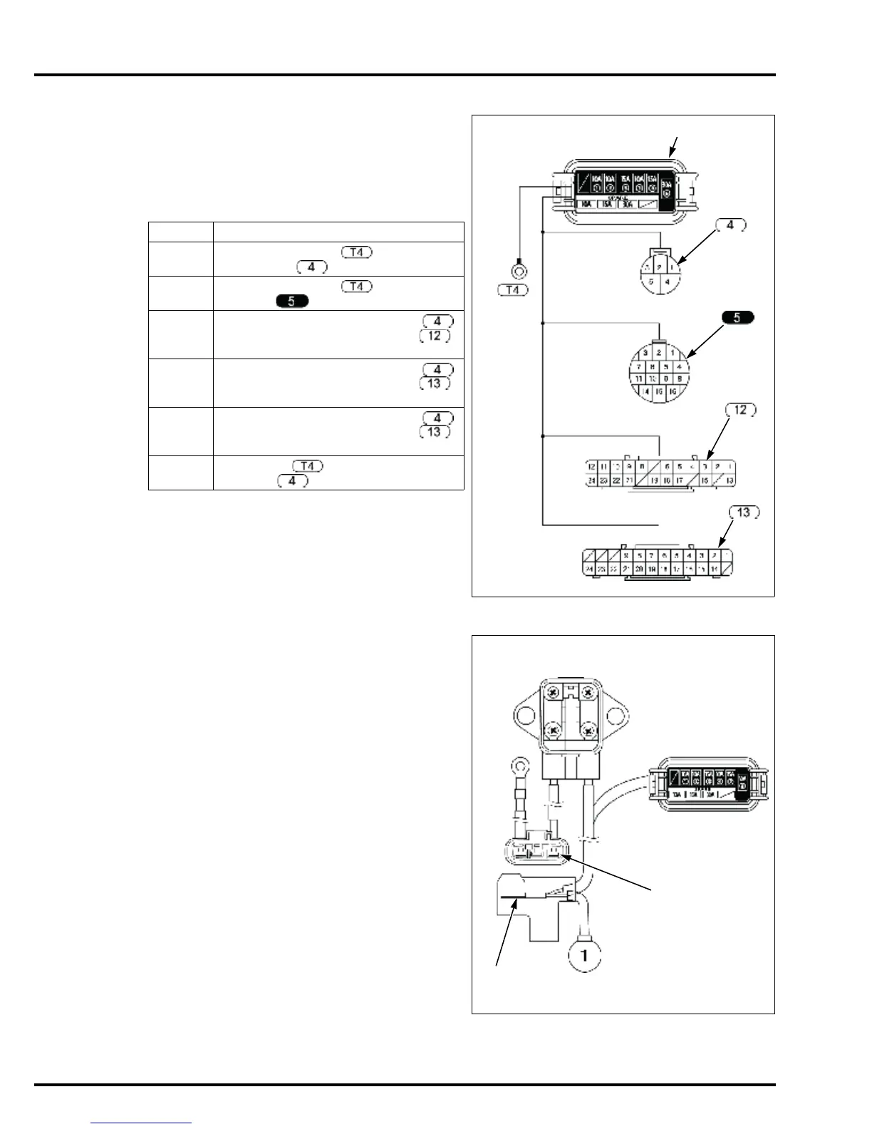
FUSE BOX INSPECTION
• Disconnect the battery cable at the negative (-)
cable before the inspection.
Remove the fuses and check for blown fuses.
If the fuses are normal, install them in the fuse box and
check for continuity between the terminals shown
below.
If there is no continuity between the terminals listed
above, replace the fuse box.
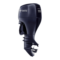
70 A FUSE BOX/FUSE INSPECTION
• Disconnect the battery cable at the negative (-)
cable before the inspecting and replacing the 70 A
fuse box.
Remove the 70 A fuse and check it for continuity.
• If there is no continuity, replace the 70 A fuse with a
new one.
• If there is continuity, install the 70 A fuse in the fuse
box. Check for continuity between the regulator/
rectifier 3P connector No.1 (White) terminal [1] and
fuse cable White terminal [2].
When a spare fuse is installed on the backside of the
cover, install so that the stamp "70 A" can be seen from
your side.
FUSE No. CHECK POINT
1 Between the terminal and fuse box
5P connector No.1 terminal.
2 Between the terminal and 14P
connector No.1 terminal.
3 Between the fuse box 5P connector
No.4 terminal and joint connector 2
No.8 terminal.
4 Between the fuse box 5P connector
No.3 terminal and joint connector 1
No.16 terminal.
5 Between the fuse box 5P connector
No.2 terminal and joint connector 1
No.24 terminal.
6 Between the and fuse box 5P
connector No.5 terminal.