10-13
dummyheaddummyhead
OTHER ELECTRICAL
PGM-FI/MAIN RELAY INSPECTION
• Check the battery condition before starting the
inspection.
• Do not connect the battery for more than 30
seconds. Wait for one minute or more before
connecting the battery again.
MAIN RELAY CIRCUIT INSPECTION
Connect the 6P connector PGM-FI/main relay side No.2
(Black/yellow) terminal to the battery (+) terminal using
a jumper wire.
Connect the 6P connector PGM-FI/main relay side No.4
(Black) terminal to the battery (-) terminal using a
jumper wire.
There should be continuity between the following
terminals of the 5P connector PGM-FI/main relay side:
• No.5 (White/yellow) – No.2 (White/green)
• No.5 (White/yellow) – No.3 (White/red)
• No.5 (White/yellow) – No.4 (White/black)
FUEL RELAY CIRCUIT INSPECTION
Connect the 5P connector PGM-FI/main relay side No.4
(White/black) terminal to the battery (+) terminal using a
jumper wire.
Connect the 6P connector PGM-FI/main relay side No.1
(Light green/black) terminal to the battery (-) terminal
using a jumper wire.
There should be continuity between the following
terminals:
STARTER RELAY CIRCUIT INSPECTION
Connect the 6P connector PGM-FI/main relay side No.5
(Black/white) terminal to the battery (+) terminal using a
jumper wire.
Connect the 6P connector PGM-FI/main relay side No.6
(Black/blue) terminal to the battery (-) terminal using a
jumper wire.
There should be continuity between the following
terminals:
If above inspection are abnormal, replace the PGM-FI/
main relay.
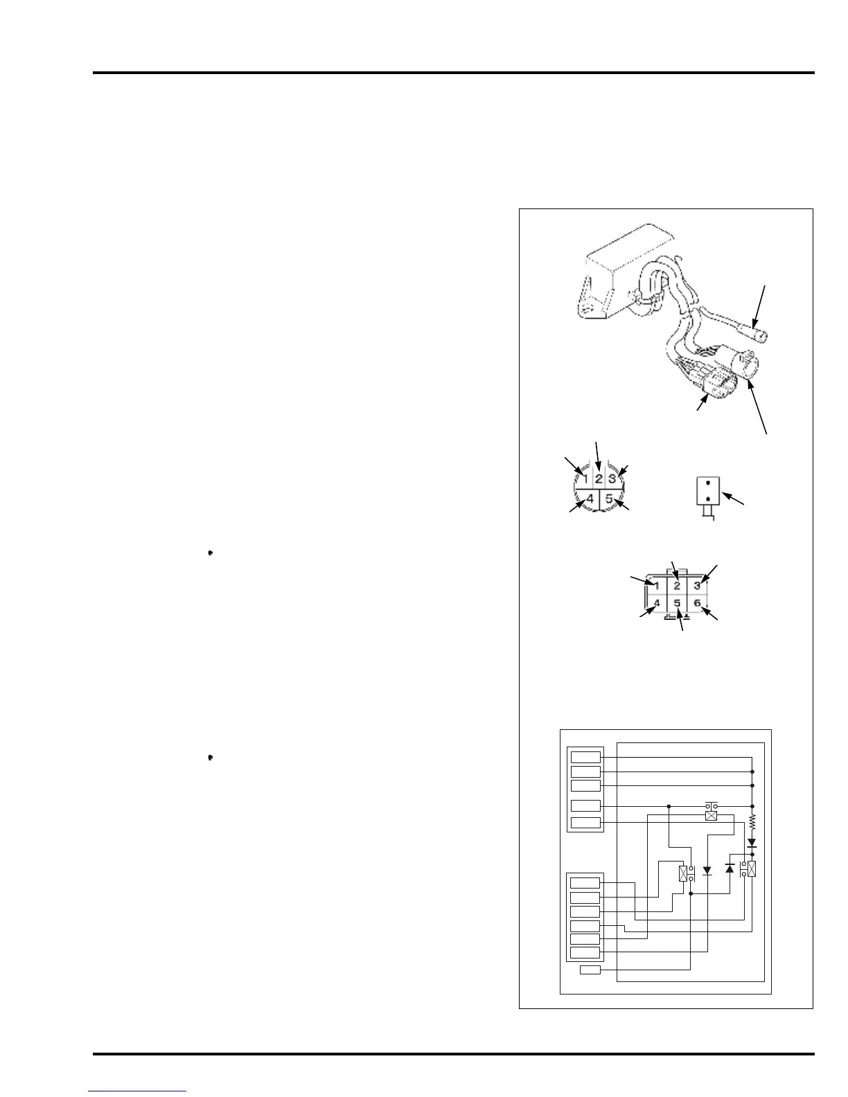
5P connector
No.1 (White/blue)
– 6P connector
No.3 (Blue/red)
5P connector
No.5 (White/yellow)
– Wire connector (White)
W/G
W/R
W/Bl
W/Y
W/Bu
Bu/R
Bl/Bu
Bl/W
Bl/Y
Bl
TERMINAL
Lg/R
Viewed from the
terminal side:
Lg/R
Bl
Bl/Bu
Bu/R
Bl/Y
W/Bl
W/Y
W/R
W/Bu
Wire
connector
(W)
W/G
Bl/W
WIRE
CONNECTOR
(White)
6P CONNECTOR
5P CONNECTOR