19-20
dummyheaddummyhead
CONTROLS
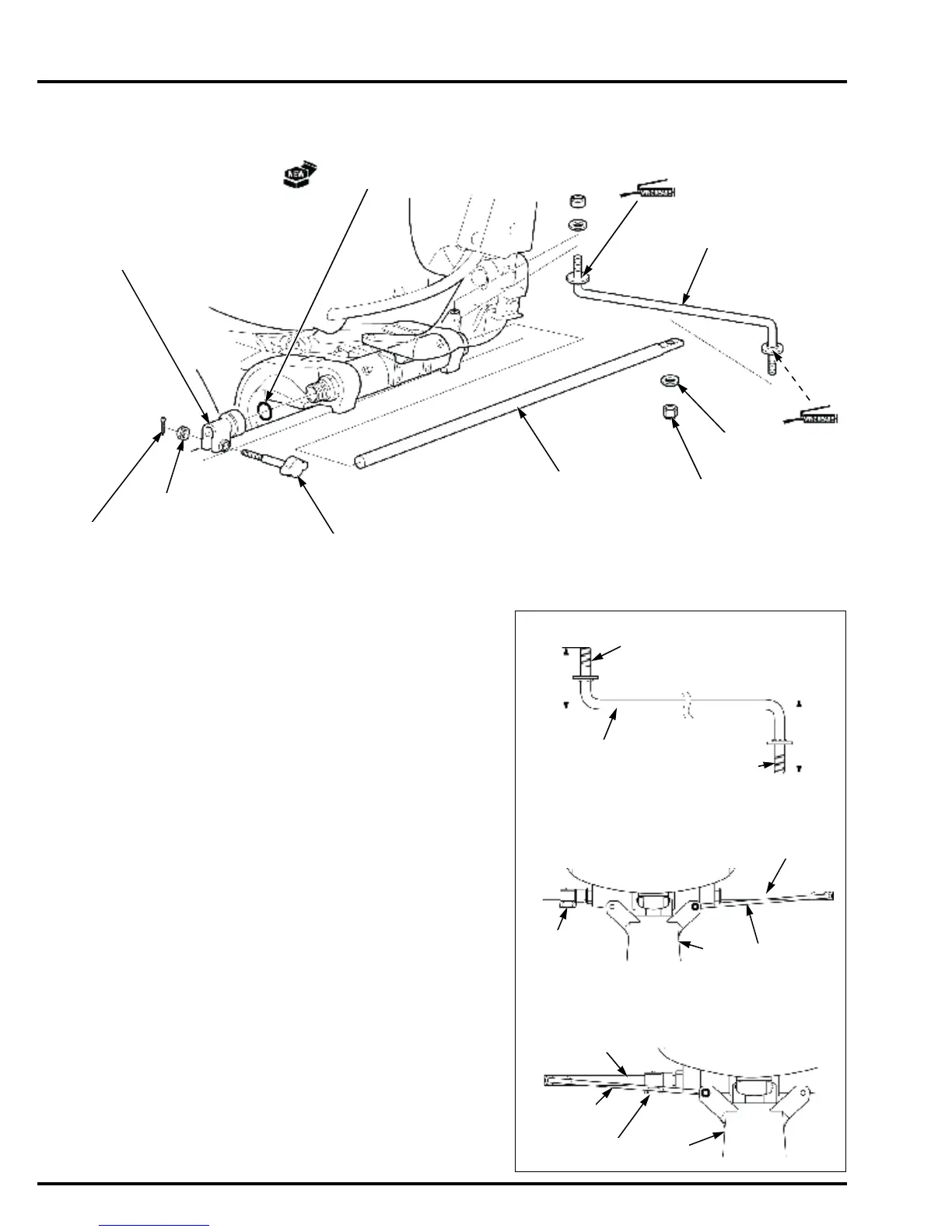
STEERING FRICTION SHAFT/ROD REMOVAL/INSTALLATION
(TILLER HANDLE TYPE)
POSITION VARIATIONS OF STEERING FRICTION ROD
• Note that the steering friction rod [1] installation
position varies, depending on the installation
direction of the steering friction shaft [2].
Install the steering friction rod in the direction shown in
Figure 1.
Install the steering friction rod on the steering bracket
[3] in the position shown in Figure 2 or 3.
Tighten the self-locking nut so that there is no play in
the steering friction rod.
After tightening, check that the steering friction shaft
and the steering friction rod move smoothly with the
friction bolt [4] loosened.
O-RING
STEERING
FRICTION BLOCK
SPLIT PIN
(2.0 mm)
NUT (6 mm)
FRICTION BOLT
STEERING
FRICTION SHAFT
SELF-LOCKING
NUT (8 mm) (2)
WASHER (8 mm)
(2)
STEERING
FRICTION ROD
Figure 1:
Figure 2:
Figure 3:
Short
Long
[1]
Steering bracket
side
Steering friction
shaft side
[2]
[1]
[1]
[3]
[3]
[2]
[4]
[4]
 Loading...