16-8
dummyheaddummyhead
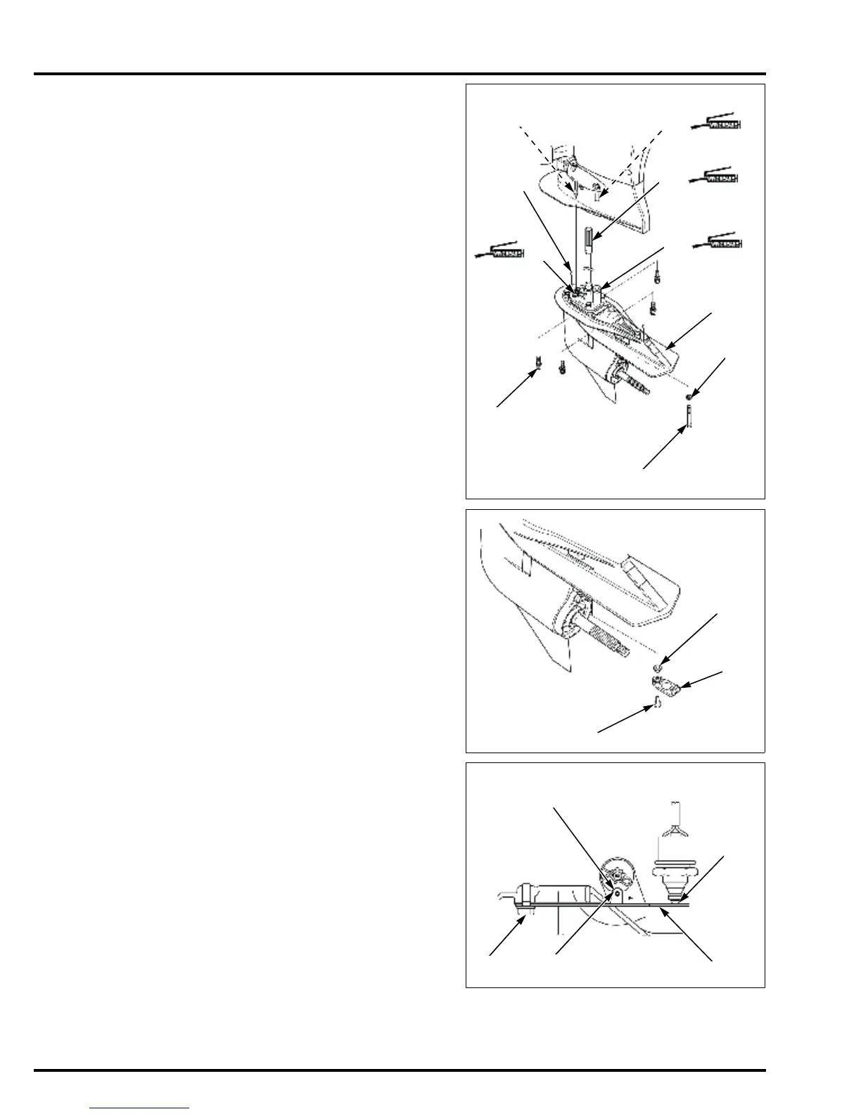
GEAR CASE
Apply marine grease to the vertical shaft spline [1] and
shift rod spline [2].
Apply marine grease to the water tube insertion part [3]
and water tube seal ring inner surface [4].
Install the vertical shaft bushing with the groove toward
the extension separator.
Apply marine grease to the inner surface to the vertical
shaft bushing (page 16-6).
Install the two dowel pins [5] on the gear case.
While aligning the water tube with the water tube seal
ring of the impeller housing, install the gear case [6] on
the outboard motor by aligning the vertical shaft with the
boss on the flywheel and aligning the shift rod spline
with the shift rod A spline [7].
Loosely tighten the for bolt/washers [8], bolt [9], and
washer [10] (LRT/LHT/LHG type only).
Loosely tighten the five self-locking nuts and five
washers (XRT type only).
Lower the outboard motor to the lowest position.
Tighten the bolts to the specified torque (LRT/LHT/LHG
type only).
Tighten the self-locking nuts to the specified torque
(XRT type only).
Install the distance collar [1] and gear case cover B [2],
and tighten the socket bolt [3] to the specified torque.
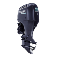
After installing the gear case, check that the tip [1] of
the neutral switch is set in the detent assisted spring [2]
securely and the detent spring roller [3] is set in the
groove [4] in the shift arm.
If the detent spring roller is not in the groove in the shift
arm, loosen the bolt [5] and move the detent spring right
or left to set the detent spring roller in the groove
securely.
Tighten the bolt.
Adjust the shift control cable (page 3-32).
TORQUE: 34 N·m (3.5 kgf·m, 25 lbf·ft)
[2]
[1]
[3]
[7]
[4]
[5]
[6]
[8]
[10]
[9]
TORQUE: 12 N·m (1.2 kgf·m, 9 lbf·ft)