TestingtheSteeringSelectorSwitch(continued)
3.IftheInfoCenterveriesthatthesteeringselectorswitchandcircuitwiring
arefunctioningcorrectly,nofurtherswitchtestingisnecessary.
4.IftheInfoCenterdeterminesthatthesteeringselectorswitchandcircuit
wiringarenotfunctioningcorrectly,proceedwiththetest.
5.Removethecontrolpaneltogetaccesstothesteeringselectorswitch;refer
toDisassemblingtheControlConsole(page6–54).
6.EnsurethatthekeyswitchisintheOFFposition.Disconnectthewireharness
electricalconnectorfromthesteeringselectorswitch.
7.ThesteeringselectorswitchterminalsareidentiedinFigure210andthe
circuitryoftheswitchisshownintheCircuitLogicT able(page5–66).With
theuseofamultimeter(ohmssetting),testtheswitchfunctionstodetermine
ifcontinuityexistsbetweenthevariousterminalsforeachswitchposition.
Checkthecontinuitybetweentheswitchterminals.
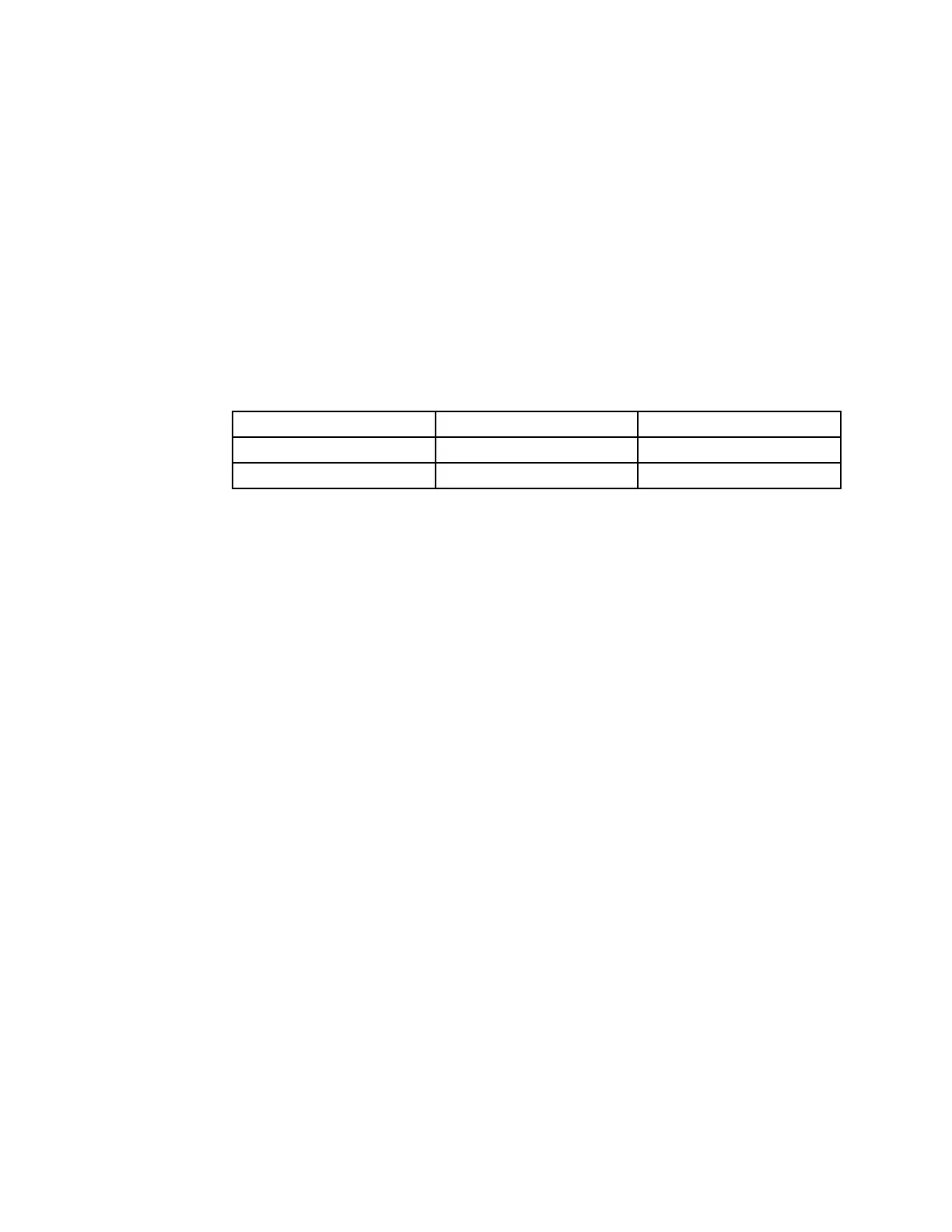
CircuitLogicTable
SwitchPositionNormalCircuitsOtherCircuits
4-WHEELSTEER
2+15+4
2-WHEELSTEER
2+35+6
Note:Thesteeringselectorswitchterminals3,4,5,and6arenotusedon
theGroundsmaster360machines.
8.Terminals7(-)and8(+)areusedfortheindicatorlightintheswitch.The
lightshouldbeilluminatedwhenthemachineisin4-wheelsteermode.T o
testtheswitchlight,apply12VDCtoterminal8(+)andgroundterminal7(-).
Thelightshouldilluminate.
9.Replacethesteeringselectorswitchiftestingdeterminesthattheswitch
isdamaged.
10.Ifthesteeringselectorswitchtestingiscorrectandacircuitproblemstill
exists,checkthewireharness;refertotheElectricalSchematicsandWire
HarnessDrawings/DiagramsinAppendixA(pageA–1)—FoldoutDrawings.
11.Afteryoucompletethetesting,connectthewireharnessconnectortothe
steeringselectorswitch.
12.Securethecontrolpaneltothemachinewiththeremovedfasteners;refer
toAssemblingtheControlConsole(page6–54).
ElectricalSystem:TestingtheElectricalComponents
Page5–66
Groundsmaster360
16225SLRevC

 Loading...


