DisassemblingtheCuttingDeckPullLinks(continued)
g036835
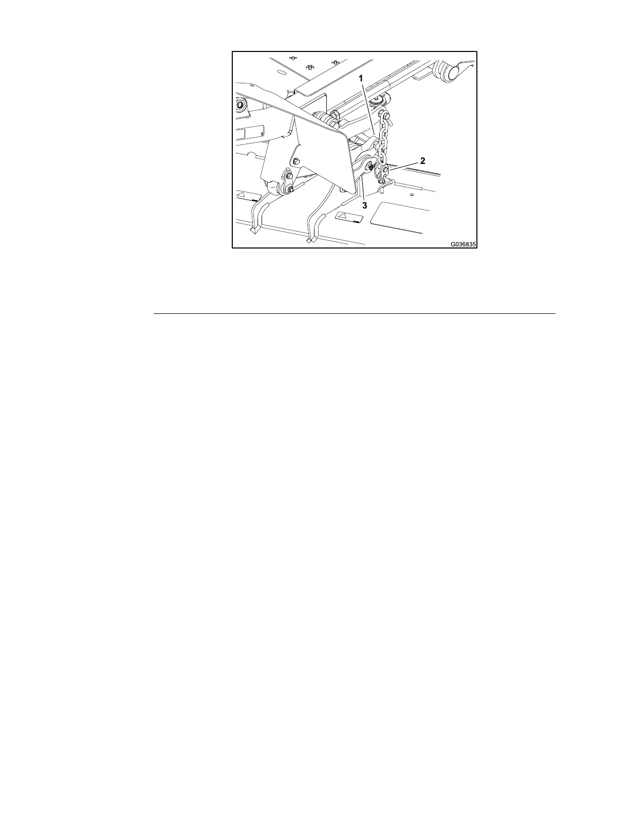
Figure318
1.Pulllink(raised)
3.Retainerpin
2.Clevisyoke
2.Removetheclevisyokefromthedecksothattheretainerpin(item3in
Figure318)canbeaccessed.
A.Removetheangenut(item12inFigure317)thatsecurestheclevis
yoketothedeck.
B.Removetheclevisyokefromthedeck.
3.Removetheboltandlocknutthatsecuretheretainerpin(item15inFigure
317)tothedeck.
4.Slidetheretainerpin(item15inFigure317)fromthedeckandpulllink.
5.Removethepulllinkwiththetorsionspring(item17inFigure317)andplain
spacerfromthedeck.
6.Inspectallthebushings(items4and18inFigure317)inthepulllink.
Note:Replacethebushingsiftheyarewornordamaged.
AssemblingtheCuttingDeckPullLinks
Note:For62inchcuttingdecks,thetorsionspring(item17inFigure317)is
paintedred.Thetorsionspringon72inchdecksispaintedblack.
1.Placetheplainspacer(item5inFigure317)insidethetorsionspringand
thentthespringandspacerintothepulllink.Ensurethatthetorsionspring
endisbelowthebolt(item1inFigure317)inthepulllink.
2.Positionthepulllinktothecuttingdeck.
3.Slidetheretainerpin(item15inFigure317)throughthecuttingdeck,pull
link,andspacer.
4.Ensurethatthetorsionspringendisbelowthebolt.Securetheretainerpin
tothedeckwiththeboltandlocknut.
5.Securetheclevisyoketothedeckwiththeangenut.
6.Installthecuttingdecktothemachine;refertotheCuttingDeckOperator’s
Manual.
7.Lubricatethepulllinkgreasettings.
8.Checkthecuttingdeckmismatchandpitch.Adjustthecuttingdeckif
necessary.
CuttingDeck:ServiceandRepairs
Page7–20
Groundsmaster360
16225SLRevC

 Loading...


