3-4 TM-500 User’s Guide
Introduction D292144.6.fm
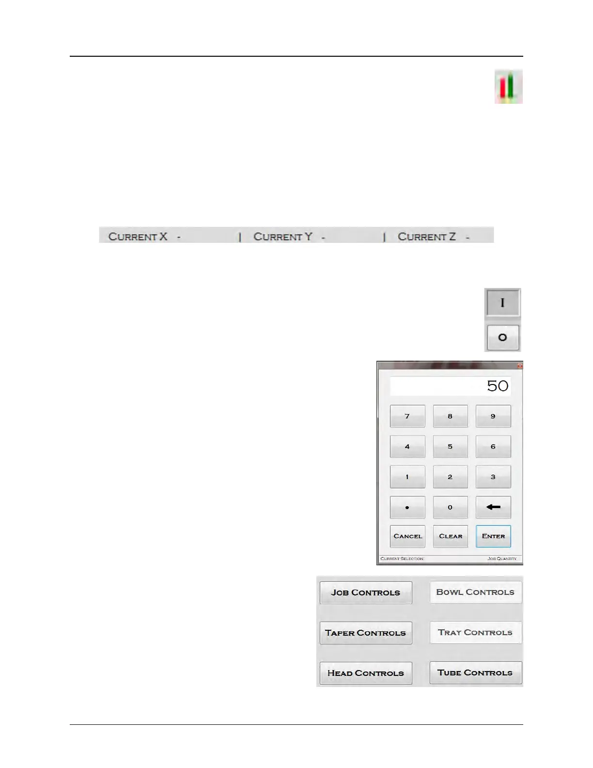
The computer Connection Status is displayed in the lower left corner of the tab. A
green bar indicates the connection is active. A red bar indicates the connection is inac-
tive. The Connection Status indicator monitors the following:
• The left bar indicates the PLC connection status.
• The right bar indicates the Motors have been Homed.
The current X Axis, Y Axis, and Z Axis Positions are displayed on the bottom right side of the
tab.
Each tab contains a variety of toggle buttons and open fields. A button is active when
the letter I (for In) appears. A button is inactive when the letter O (for Out) appears.
Click in any text box to open a keypad and enter the appropri-
ate value.
Control buttons or fields may appear grayed out
if that particular module is not installed or if the
field is not enabled for the current access level
by the Super User.
In the example on the right, the Job, Taper, Head
and Tube Controls are active. The Bowl and
Tray Module Controls are not installed/disabled.


 To Next Page