2. Press UP or DOWN to select the proper CN Node number, press ENTER, and Ping a
3. Press UP, and then press UP or DOWN to select the port of interest.
4. Press ENTER, and the selected CN Card displays. The ping information scrolls across
the display. See Figure 4.
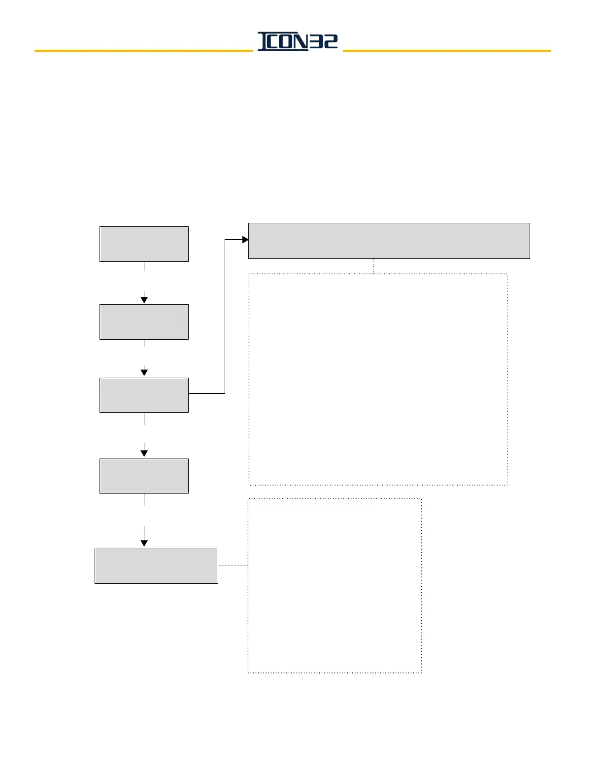
DCN –Display Stats
Up: Next DN: Prev
CN Node: (0-11)
Up: + DN: -
Ping a Port?
Up: Yes DN: No
YES
CNn Port: (0-16)
UP: + DN: -
NO
CN:n NodeName----Online:n Pcks:n Ch:n v:n uPLPC23xxSP:n TP:n
Ports: n, n+1, n+2, 255, n+4 ...
CN: CN Node ID (selected).
NodeName: name assigned to the node selected.
----Online: online status;
1 = online, 0 = offline
Pcks: number of data packets received.
Ch: CAN channel node is assigned;
2 = CCH/CCL, 3 = HC1H/HC1L
v : node software version.
uPLPC23xx: node hardware version.
SP: number of Shared Ports assigned the node.
TP: number of Total Ports assigned the node.
Ports: lists the control system port number assigned
to the node’s physical I/O port (255 is an unassigned port).
A node card having 12 ports will have 12 ports listed,
only the used ports will have a port number assigned.
CN: CN Node selected previously.
Port: Port number selected previously.
v: node software version.
LPC23xx: node hardware version.
Bit: bit assignment.
IOName: I/O name assigned to bit.
Data: indicates I/O state;
1–inactive, 0–active.
IO: indicates I/O as input or output;
1–input, 0–output.
Call: indicates I/O as a hall/car call;
1–call, 0–non-call.
ENTER
ENTER
ENTER
CNn Portn v:# LPC23xx
**Bit#, IOName, Data, IO, Call