INSTALLATION
Vertical Express Product Manual 1-3 88600 v.1.0
Installation Section Preliminary Installation
Preliminary Installation
Install the following items. Refer to the Vertical Express Installation Manual (located
at: http://www.verticalxpress.com/component_manuals/Installation Manual), and
the installation instructions that ship with the equipment.
• Pit template (if provided), pit channel, and buffers
• Jack, jack follower guides (as required), rail brackets and rails
• Car sling and platform
•Power unit and controller
• Fluid line (jack line)
Prepare for Temporary Operation
1. Turn OFF, Lockout, and Tagout the mainline disconnect.
2. Pipe and install power from the mainline disconnect to the controller.
See Figure 2 on page 1-4.
• Conduit for the wires from the mainline disconnect must be installed on the
same side of the controller cabinet as the motor starter.
• The fourth wire ground from the disconnect is to be landed on the dedicated
ground bar of the controller, not the motor starter heatsink.
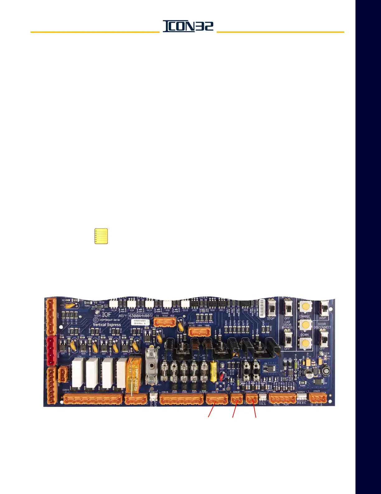
3. Verify that CON19, CON20, and CON21 are removed on the IOF Card. See
Figure 1.
Figure 1 - IOF Card Connectors