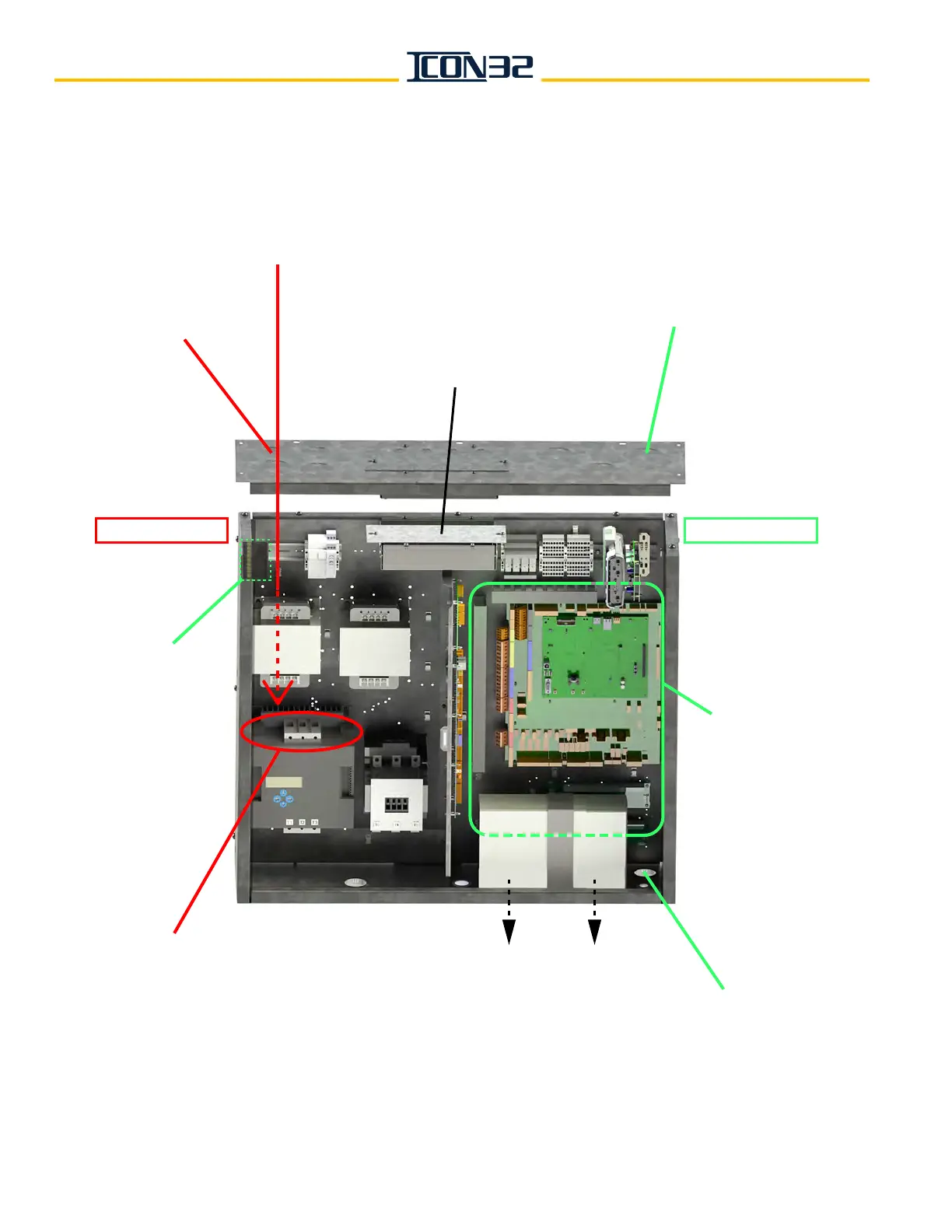
Mainline Disconnect Power
Connection to Controller
UPS Electrical Cords
Pass Through Knockout
UPS installed on the underside of the controller
(use the shipping bracket and screws to mount)
High Voltage In
(from knockouts in this
corner of the controller)
High Voltage Wire Routing
(straight down to the
electronic motor or
contactor starter)
Trades Access Terminal Strip
(through controller top panel)
Low Voltage In
(from knockouts on this
side of the controller)
NOTE: If the THY-02 Card (6300ACA2)
obstructs the low voltage wiring,
move the card to the DIN rail.
Ground Bar
Low Voltage
Wire Routing
(as needed)
HIGH VOLTAGE SIDE LOW VOLTAGE SIDE