INSTALLATION
Vertical Express Product Manual 1-11 88600 v.1.0
Installation Section Temporary Operation
Electronic Starter Setup
(continued)
6. Press
once and OVERLOAD AMPS displays.
a. If the value is correct, skip to Step 8.
b. If the value is not correct, continue to Step 7.
7. Press
once to access the value.
a. Press
or to adjust the value of the flashing digit.
b. Press
to move to the next digit.
8. Press
to exit to the PARAMETERS Menu.
A prompt to ACCEPT or REJECT the change appears. Press
to accept, or to
reject and correct the parameter.
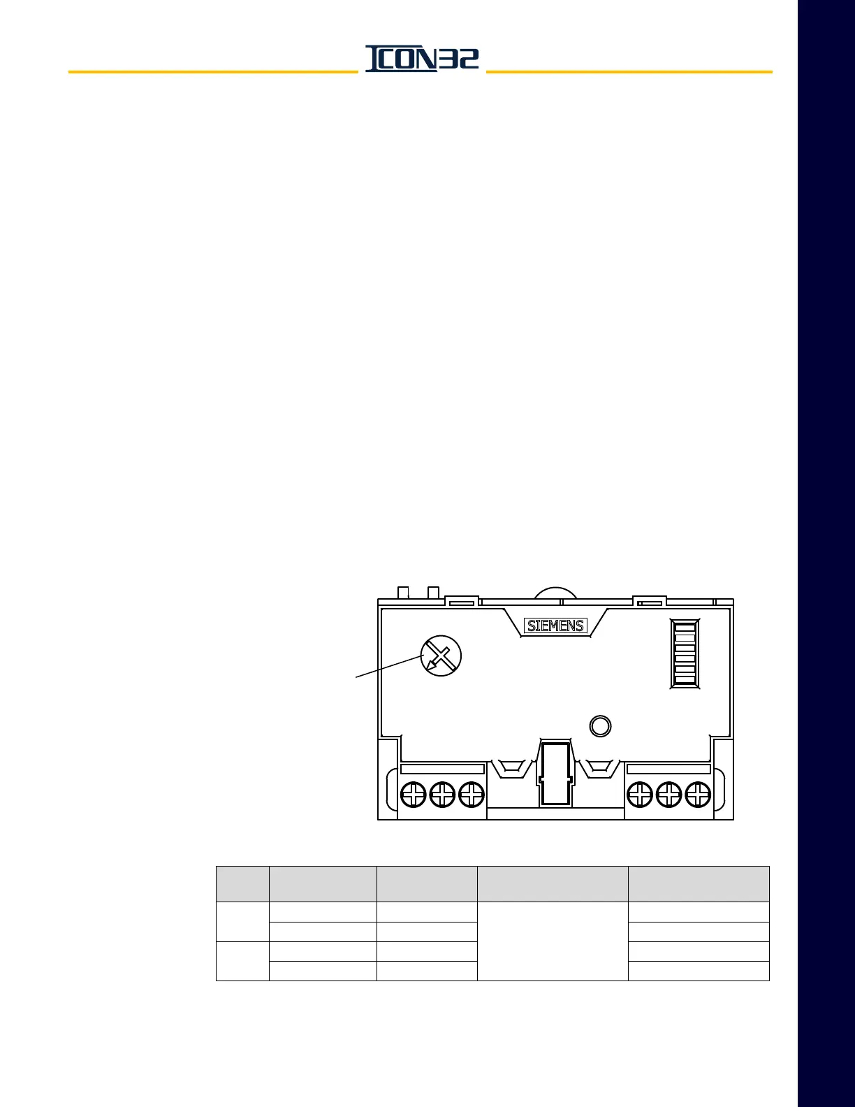
Mechanical Starter Set Up with ESP200 Overloads
Overload relay current settings are preset by Manufacturing. The following initial
adjustment can also be used during temporary operation for jobs that trip overloads,
but the actual overload current will be set during final adjustment.
1. Use Table 1 below or Table 2 on page 1 - 12 to determine the overload relay cur-
rent setting based on the motor horsepower and voltage or nameplate amps.
2. Set the full load amps adjustment dial to the overload current setting from
Step 1. See Figure 10.
Figure 10 - ESP200 Overload Adjustment
Table 1 - Overload Specifications For Single Phase Motors
Full Load Amps
Adjustment Dial
Motor
HP
Motor Voltage
(50 or 60 Hz)
NEC Motor NP
Rated Amps
Wiring
Configuration
Overload
Current Setting
7.5
200V/208V 46
Special,
See Wiring Diagrams
50
230 40 43
10
200V/208V 58 62
230 50 54