ADJUSTMENT
Vertical Express Product Manual 2-7 88500 v.1.0
Adjustment Section Preliminary Adjustment
Software Verification Procedure
(continued)
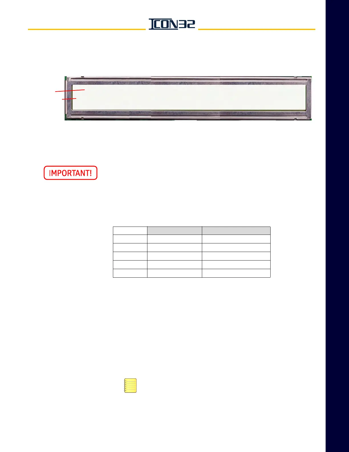
c. Press UP until VER displays, press ENTER, and window displays this data:
This controller contains software that is under AECO A17.7 Control. When
replacing boards or functions involving this controlled software, verify that
the replacement or updated software is the same version listed on the
580AMY marker attached to the controller.
Fill out the following chart. If any processor/node reports version zero (0), the device
is not communicating; see Troubleshooting.
Safety Processor Verification
1. Verify that the Controller Inspection Switch is on INSP.
2. Use the following information to verify that either the SP Good LED or the SP Bad
LED is illuminated.
• SP Good LED illuminated: Continue to CAN Node Address Assignment on
page 2-8.
• SP Bad LED illuminated: Continue to CAN Node Address Assignment on
page 2-8.
The SP Bad should be glowing until the safety nodes are online and
indicate a ready to run condition. Configure the Safety Processor if
the IOF Card was exchanged with another controller.
• SP Good/SP Bad LEDs toggle back and forth: The Safety Processor is not
configured. Continue to the next procedure.
Top Line
Bottom Line
v = version
x = version number
r = revision
y = revision number
• If any of the safety nodes are offline, the car is shutdown and a fault is logged.
• Background color removed for clarity.
JOB:xxxnnn CPUC:vxry, CPUCfpga: vxry, IOFfpga:vxry
SP: vxry, SP:fpga:0, NP: vxry, CWILA:vx, CWILB:VX, SELA:vx,
SELB:vx, HNBTopA: vx, HNBTopB:vx, HNBBotA:vx, HNBBotB: vx
Definition Installed Software Version
CPUC Controller Generic
SP Safety Processor
NP Normal Processor
SELA Selector Node A
CWIL/DPIA DPIA Node A