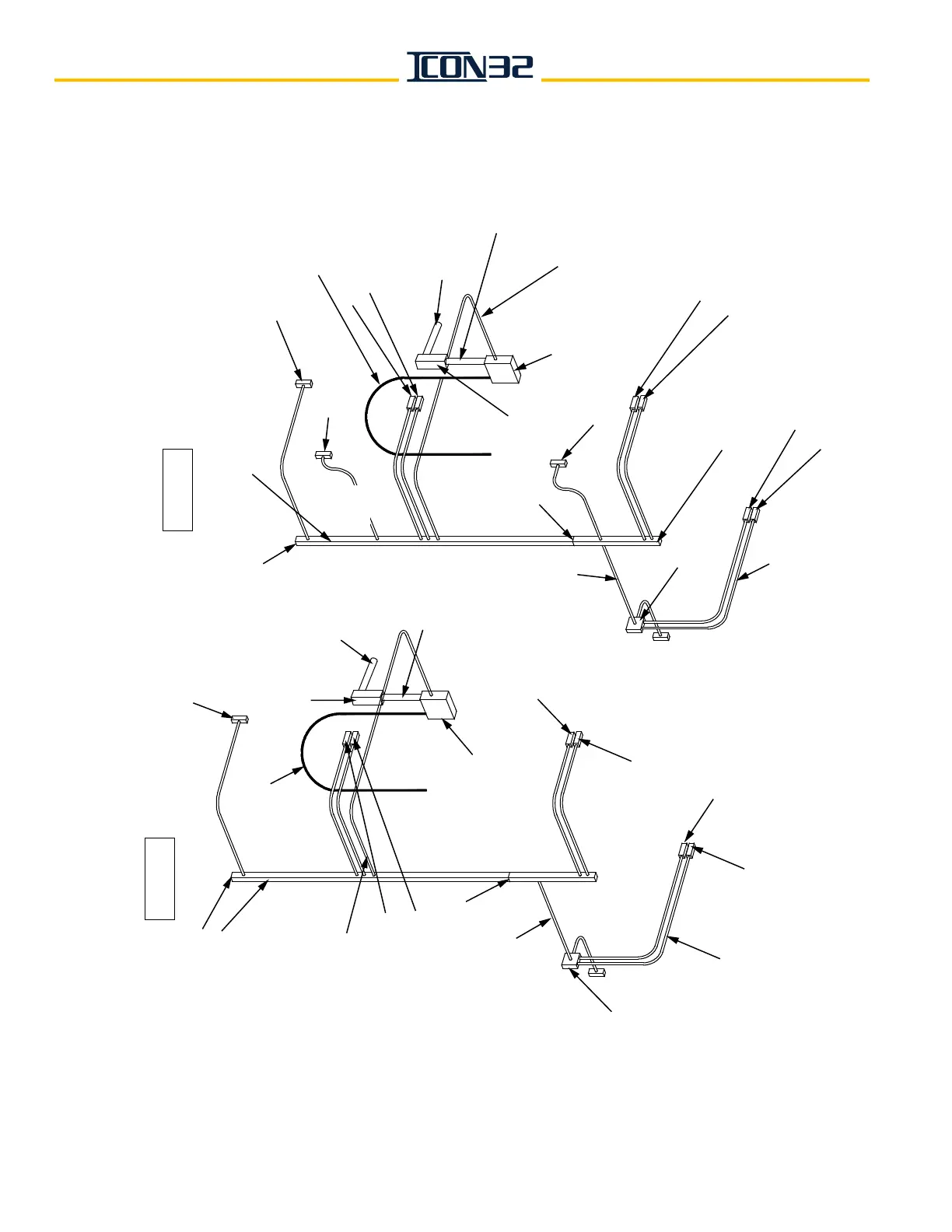
½"
FLEX (typical)
6" X 6"
Outlet Box
¾" EMT
Car
2
Front
PI
or Combo PI/Lantern
Car 2
Front Interlock
Car
1 Front PI
or Combo PI/Lantern
Car 1
Front Interlock
Car 2 Pit
Stop Switch
Front
Hall Station
½" FLEX (typ.)
Car 1 Pit
Stop Switch
Splice
Pull Box
2½" x 4" Wireway
Connector (typ.)
2½" x 4" Wireway
End Cap
2½" EMT or
2½" x 4"
Wireway
Mid Hatch
Junction Box
1" EMT Run
from Mid Hatch Box
to 2½" x 4" Wireway,
run between door
openings, or as req.
FOR NON-MULTIPLEX HOISTWAYS
Each car has a vertical
2½" x 4" wireway riser.
Common functions are wired from one of the car’s risers,
and then cross-wired from one controller to the other controller in the machine room.
Traveling Cable
Traveling Cable
Pull Box
¾" EMT
6" X 6"
Outlet Box
Car
1 Rear PI or Combo PI/Lantern
Car 1
Rear Interlock
Car
1 Front PI or
Combo PI/Lantern
Car 1
Front Interlock
Front
Hall
Station
2½" x 4" Wireway Connector (typ.)
End Cap
CAR 1
CAR 2
2½" x 4"
Wireway
End Cap
To
Machine
Room
½"
FLEX
1" EMT Run
from Mid Hatch Box
to 2½" x 4" Wireway,
run between door
openings, or as req.
Car
2 Rear PI or Combo PI/Lantern
Car 2
Rear Interlock
2½" EMT or
2½" x 4"
Wireway
To
Machine
Room
Mid Hatch
Junction Box
Splice
Car
2
Front
PI
or Combo PI/Lantern
Car 2
Front Interlock