TROUBLESHOOTING
Vertical Express Product Manual 4-7 88500 v.1.0
Troubleshooting Section CAN Channel Resistive Loading Verification
CAN Channel Resistive Loading Verification
After correcting CAN loading, issue a TECC Command to ensure the cards are properly configured.
Car CAN Channel 2
• The CAN Channel Troubleshooting Guide is located on page 4-10.
60 ohms is the optimal loading for CAN communications.
1. Position the car so that there is access to the operating panels, and verify that
the controller is de-energized.
2. Turn OFF, Lockout, and Tagout the mainline disconnect.
3. In the COP, verify that a 121 ohm axial leaded resistor is installed across the CCH
and CCL rail terminals.
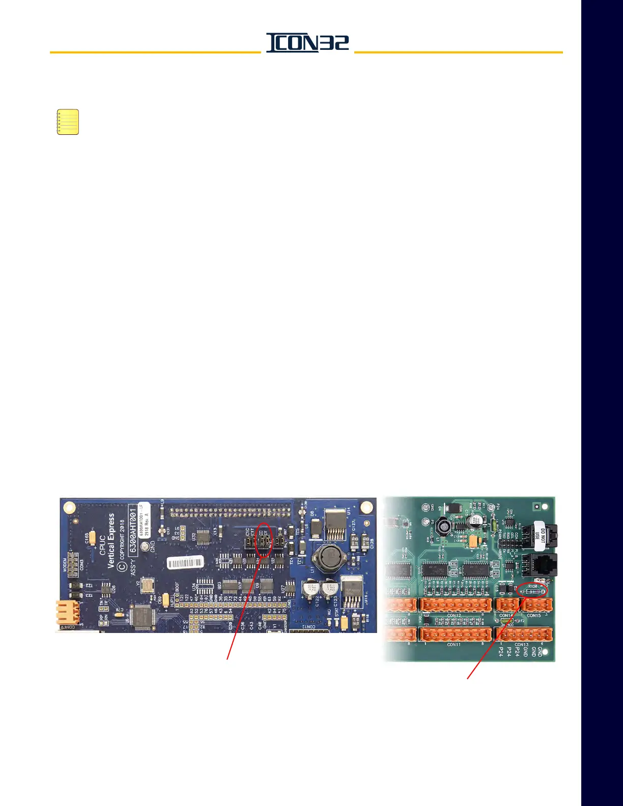
4. In the controller, verify that the CPUC Card jumpers CCC and CCT are ON. See
Figure 1.
5. In the controller, verify that R120 on the MODCTRL1 CNA Card is not installed.
The CNA Card is located on the center divider panel.
6. For cars with more than one CNA assigned to the Car CAN Channel:
a. Verify that the nodes are connected in parallel (daisy-chained).
b. Verify that none of the CNA Cards have R120 populated.
Figure 1 - CPUC and CNA Cards
CPUC CARD
JUMPER CCC=ON
JUMPER CCT=ON
CNA CARD
R120 Node