I-2/I-3 Valve Installation Section
©Vertical Express 1-14 Printed in USA April 2020
Pump Motor Rotation
(continued)
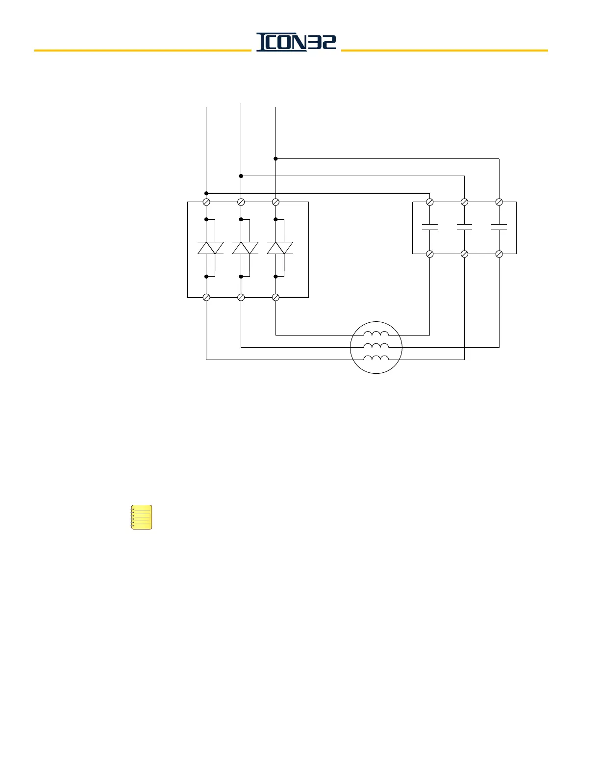
Figure 11 - Electronic Starter Pump Motor Wiring Diagram
I-2/I-3 Valve
The I-2/I-3 Valve is preset by Manufacturing, assembled on the power unit, and has been
tested and adjusted. The presets are attached inside the controller, ensure movement of
the car, and reduce final adjustment time.
• The I-2/I-3 Valve requires a minimum static system pressure of 90 PSI to function
properly.
• Adjust and confirm the Relief Pressure and Low Pressure on each job—at this
time if possible.
• If the empty sling is too light to achieve 90 PSI, defer the Low Pressure adjustment
until the cab is installed and 90 PSI is achieved.
• Valves by other manufacturers: refer to the applicable valve product manual for
initial setup - Bypass/Low Pressure and Relief Pressure Adjustments.
Electronic
Motor
Starter
L1 L2 L3
T1 T2 T3
MC2
T3
T1
T2
T4
T5
T6
5
2
31
46