Hall Lanterns,
Position Indicators
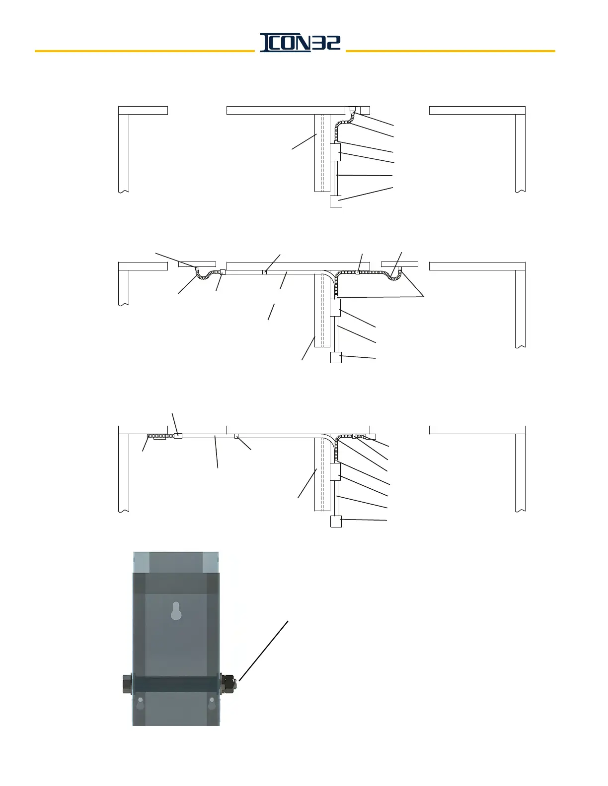
Installation
½" or
¾
" EMT Conduit with
½" or
¾
"
Straight Connector (EMT)
½" or
¾
" Straight Connector (Flex)
Divider Beam
2
½
" X 4
"
Wireway
½" or
¾" Straight
Connector (Flex)
¾" EMT & Fittings
¾" Flex Conduit
4" x 4" Outlet Box
¾
" Clamp
½" or
¾
"
Flex Conduit
¾
" Clamp
Hall Station,
Fire Service
Switch
Installation
Divider Beam
½
" Flex Conduit
½" Straight Connector (Flex)
2
½
" X 4
"
Wireway
½" Straight Connector (Flex)
4" x 4" Outlet Box
¾" EMT & Fittings
Door Interlock
Installation
¾
" Clamp
½
" Clamp
Divider Beam
½
" Flex Conduit
½
" Straight Connector (Flex)
½" Straight Connector (Flex)
2
½
" X 4
"
Wireway
¾" EMT & Fittings
4" x 4" Outlet Box
½
"
EMT Conduit with
½
"
Straight Connector (EMT)
½
" Combination Coupling
½
" Flex Conduit
Strain Bolt
Installation
Install strain bolt in the wireway
as shown.
Remove one knockout
on each side of the
wireway and install the strain bolt. Secure
hoistway wires to the bolt with
tie wraps.
¾
" Combination Coupling