ADJUSTMENT
Vertical Express Product Manual 2-11 88500 v.1.0
Adjustment Section Preliminary Adjustment
CAN Node Address Assignment
(continued)
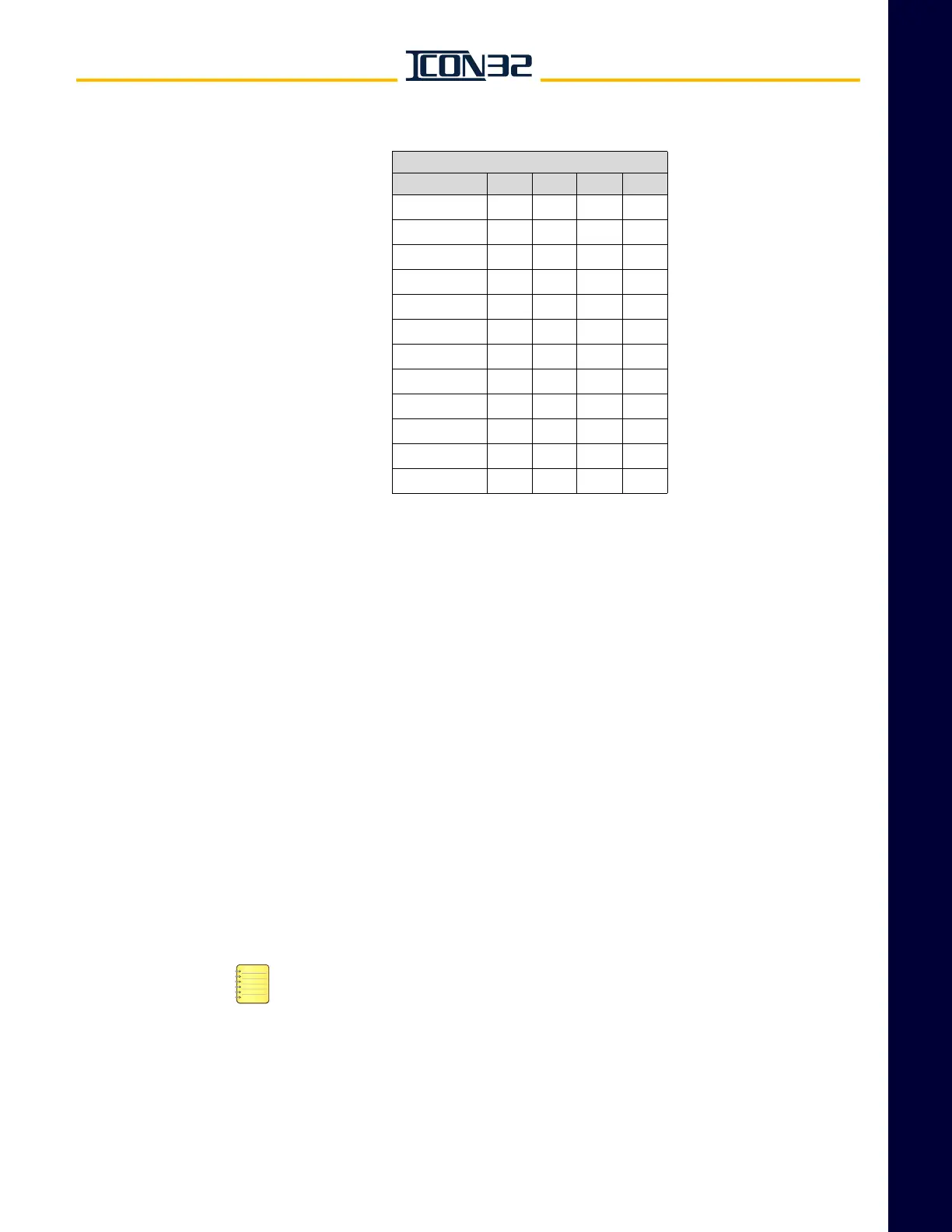
Table 1 - CN Card Node Addressing
12. Verify that JP14 is ON pins 1-2.
13. Verify that JP8 is OFF.
14. Confirm any CAN node designated "CH:2" is wired to CCH/CCL. See job prints.
15. Confirm any CAN node designated "CH:3" is wired to HC1H/HC1L. See the job
prints.
Verify Proper Resistive Loading for the CAN Channels
Perform this procedure each time a controller or a CAN node is added to the CAN
channels.
1. Turn OFF, Lockout, and Tagout the mainline disconnect. All cars in the group
must be de-energized to correctly measure resistance on the Hall and Group
CAN channels.
2. Verify that all cars in the group are cross-connected as follows:
a. CON40 on the IOF, RCH/RCL, P24XC, and G24.
HC1H/HC1L is only necessary if that channel has been assigned node(s), see
CAN Node Address Assignment procedure.
b. Fire Service I/O from the Trades Access Panel.
c. All Group I/O: Hall Calls, Fire Service Inputs, Security, etc.
d. EPNP - only if alternate power is used for Emergency Power. Do not cross-
connect EPNP for battery lowering cars.
CN Card Node Addressing
JP7 JP6 JP5 JP4
CN Card 0 OFF OFF OFF OFF
CN Card 1 OFF OFF OFF ON
CN Card 2 OFF OFF ON OFF
CN Card 3 OFF OFF ON ON
CN Card 4 OFF ON OFF OFF
CN Card 5 OFF ON OFF ON
CN Card 6 OFF ON ON OFF
CN Card 7 OFF ON ON ON
CN Card 8 ON OFF OFF OFF
CN Card 9 ON OFF OFF ON
CN Card 10 ON OFF ON OFF
CN Card 11 ON OFF ON ON