Preliminary Adjustment Adjustment Section
©Vertical Express 2-10 Printed in USA April 2020
CAN Node Address Assignment
(continued)
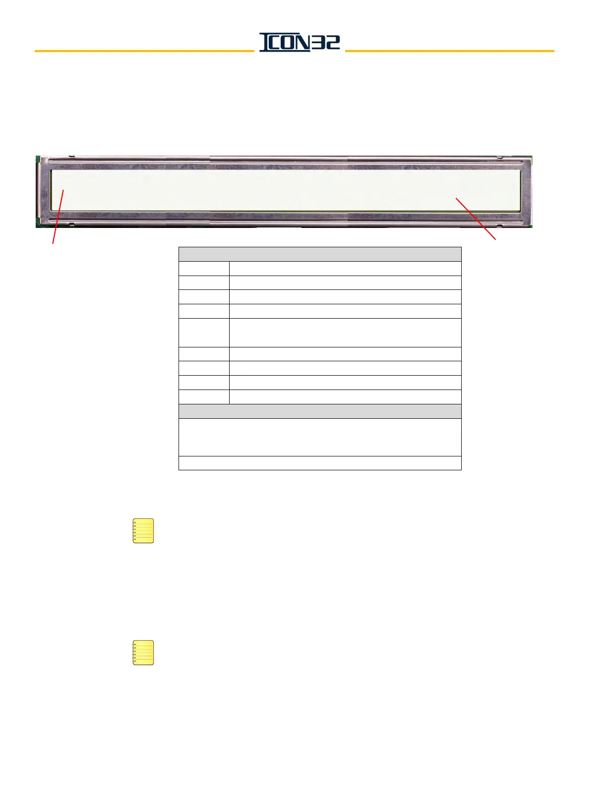
The CN Node ID (selected from step 6) displays, followed by its SmartName. The DCN information will begin to scroll
from left to right on both lines at different rates, see image below. Pressing UP or DOWN will pause the scroll until the
UP or DOWN is pressed again.
8. Record the CN, the SmartName, and the CH information.
ICON32 Controllers should have the MODCTRL1 node on CH: 2 — the main interface node
for the typical job mounted on the center divider of the controller.
9. Press ESC.
10. Repeat step 6 through step 9 for each node 0-11.
11. Verify the addressing jumpers for any CAN Node Card used in the system. See Table 1
on page 6-11.
A CAN node may be CN, CNA, or any future CAN Node Card. When the jumpers are
populated on the card, the jumpers assigned functions are the same across the card
assemblies.
CN:1 CNAMAIN1--- ONLINE:1 Pcks:86 CH:2 v:32 uP18Fxxxx SP:0 TP:12
Ports: 3, 24, 25, 26, 2, 23, 24, 2, 255, 255, 255
Top Line Display
CN: The node ID
CNA-
SmartName
Online: Online status: 0 = Offline, 1 = Online
Pcks: # of received data packets
CH:
CAN channel from which the node is assigned to
communicate: 2 = Car, 3 = Hall
V: Software version
uP18Fxxxx microprocessor version for that node
SP: # of shared ports
TP: # of total ports assigned to the node
Bottom Line Display
Port assignments for ports 0 (zero) through 15 = the numbers
represent the port number of the I/O map the port is to use, and all
unused ports for a node receive a port assignment of 255.
CNA Cards always have 12 total ports assigned to them.
Bottom
Line
Display
Top Line Display