Configure the CAN Nodes Troubleshooting Section
©Vertical Express 4-6 Printed in USA April 2020
CAN Node Address Assignment
(continued)
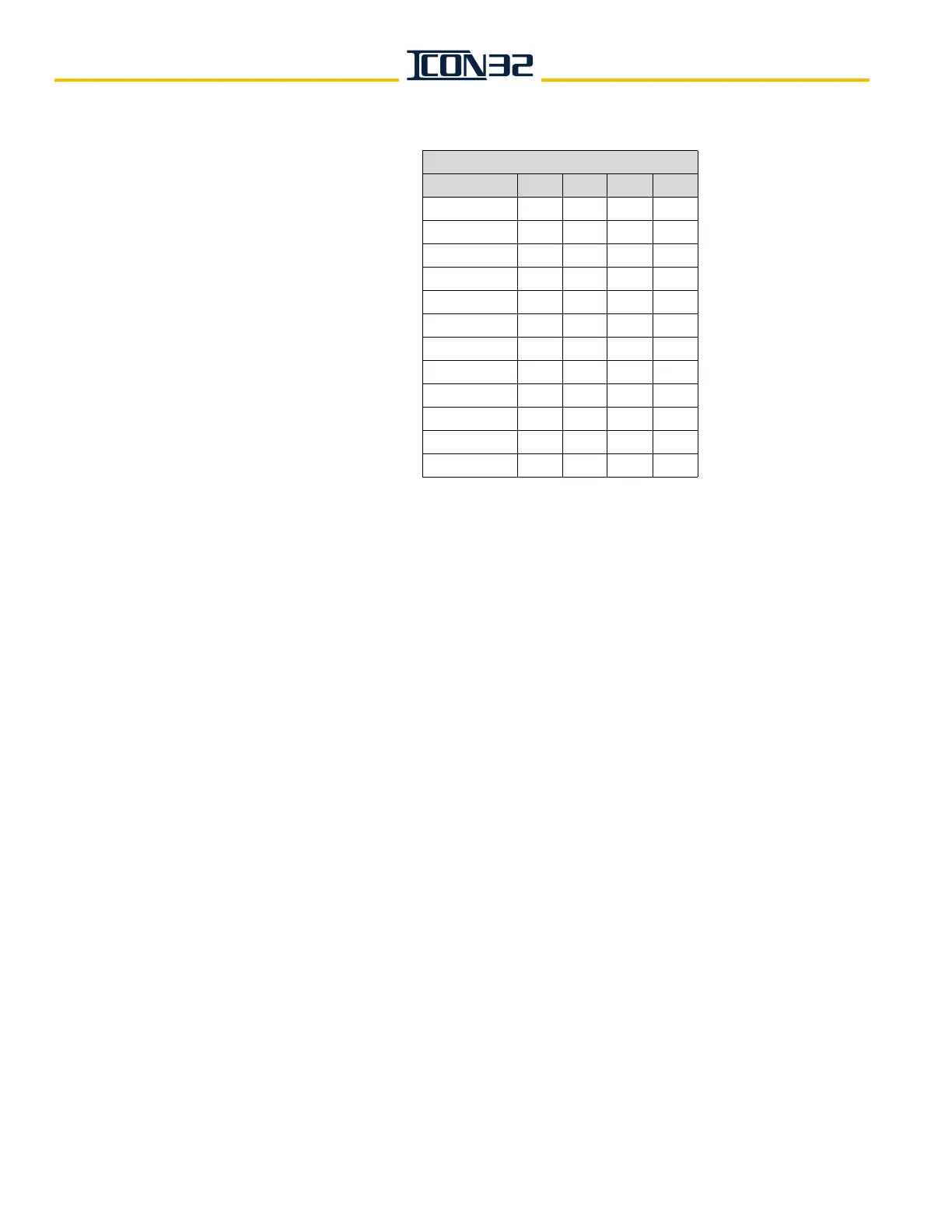
Table 1 - CN Card Node Addressing
12. Verify that JP14 is ON pins 1-2.
13. Verify that JP8 is OFF.
14. Confirm that any CAN Node designated "CH:2" is wired to CCH/CCL. See job prints.
15. Confirm that any CAN Node designated "CH:3" is wired to HC1H/HC1L. See job prints.
16. Remove power from the controller.
17. Check resistance between CCH and CCL on the IOF (60 ohms +/-3 ohms is typical).
• If the resistance is correct, continue this procedure.
• If the resistance is not correct, go to CAN Channel Resistive Loading Verification
on page 4-7.
18. If any node has been designated "CH:3," remove power from all controllers
currently
crossed connected within the
group.
19. Check resistance between HC1H and HC1L on the IOF (60 ohms +/-3 ohms is typical).
• If the resistance is correct, continue this procedure.
• If the resistance is not correct, go to go to CAN Channel Resistive Loading Verifica-
tion on page 4-7.
20. Restore power to any controllers previously de-energized.
21. Issue a TECC Command.
Block Select Adjustments > Commands Startup > TECC.
22. Issue a DCN Command.
Block Select Adjustments > Commands Startup > DCN.
23. Verify that all nodes with SmartName previously recorded from step 8 on page 4-5 are
reported as being ONLINE:1.
CN Card Node Addressing
JP7 JP6 JP5 JP4
CN Card 0 Off Off Off Off
CN Card 1 Off Off Off On
CN Card 2 Off Off On Off
CN Card 3 Off Off On On
CN Card 4 Off On Off Off
CN Card 5 Off On Off On
CN Card 6 Off On On Off
CN Card 7 OffOnOnOn
CN Card 8 On Off Off Off
CN Card 9 On Off Off On
CN Card 10 On Off On Off
CN Card 11 On Off On On