CN:n NodeName----Online:n Pcks:n Ch:n v:n uPLPC23xx SP:n TP:n
Ports: n, n+1, n+2, 255, n+4
CN: CN Node ID (selected).
NodeName : name assigned to the node selected.
----Online: online status;
1 = online, 0 = offline
Pcks : number of data packets received.
Ch : CAN channel node is assigned;
2 = CCH/CCL, 3 = HC1H/HC1L
v : node software version.
uPLPC23xx : node hardware version.
SP : number of Shared Ports assigned the node.
TP : number of Total Ports assigned the node.
Ports : lists the control system port number
assigned to the node’s physical I/O port. (255
indicates an unassigned port.) A node card having
12 ports will have 12 ports listed, only the used
ports will have a port numbers assigned them.
CN : CN Node selected previously.
Port : Port number selected previously.
v : node software version.
LPC23xx : node hardware version.
Bit : bit assignment.
IOName : I/O name assigned to bit.
Data : indicates I/O state;
1- inactive, 0 - active.
IO : indicates I/O as input or output;
1 – input, 0 – output.
Call : indicates I/O as a hall/car call;
1 – call, 0 – non-call
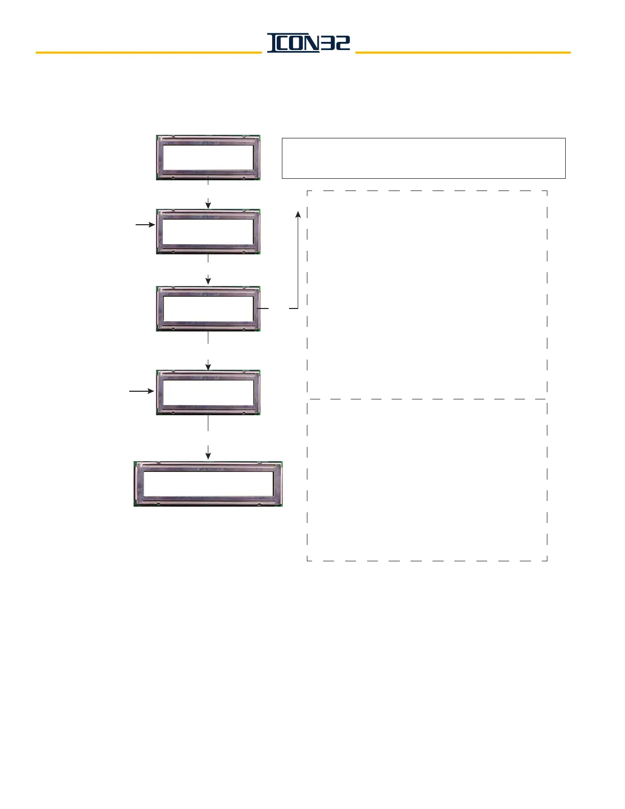
CN Node: (0-11)
Up: + DN:
ENTER
Ping a Port?
Up: Yes DN: No
CNn Port: (0-16)
UP: + DN: -
CNn Portn v:# LPC23xx
**Bit#, IOName, Data, IO, Call
ENTER
Yes
No/
ENTER
CN Node previously
chosen is the
indicated (CNn).
Select the Port of
interest from
chosen CN.
ENTER
Select CN Node
number of interest.
DCN – Display Stats
UP: Next DN: Prev