Industrial 1.6L Engine Electrical 3-17
Notice: Always turn the ignition switch OFF when
connecting or disconnecting batteries, battery charg-
ers, or jumper cables. Failure to do so may damage
the electronic control unit or other electrical
components.
1. Disconnect the negative battery cable.
2. Ensure that the ignition switch is OFF, and
that all electrical accessories are OFF.
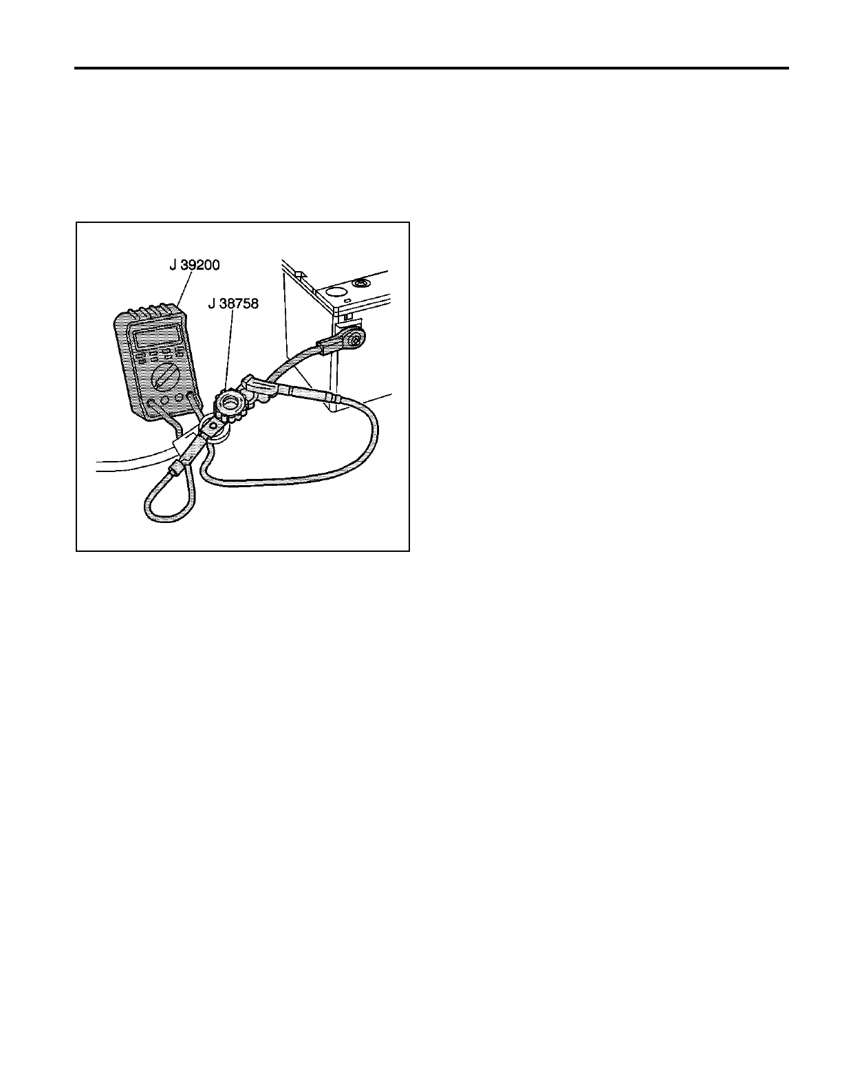
3. Install the male end of the J 38758 to the negative
battery terminal.
4. Turn the J 38758 test switch to the OFF position.
5. Connect the negative battery cable to the female
end of the J 38758 test switch.
6. Turn the J 38758 test switch to the ON position.
Notice: Do not turn the parasitic draw test switch to the
OFF position with the engine running. Damage will
occur to the equipment’s electrical system.
7. Test the electrical system by running the engine
and operating the equipment.
8. Turn the ignition switch to the LOCK position and
remove the key. Turn all electrical accessories off.
9. In order to avoid a false reading, wait 15 minutes
for all components to power down before continu-
ing this test.
10. Before connecting the ammeter, use the following
procedure to determine whether or not the current
drain is less than 10 amps:
10.1. Connect a jumper wire with an in–line 10-
amp fuse or circuit breaker to the termi-
nals of the J 38758 test switch.
10.2. Turn the J 38758 test switch to the OFF
position.
10.3. Wait 10 seconds.
11. If the fuse in the jumper wire does not blow, turn
the J 38758 test switch ON, set the J 39200 to the
10–amp scale and connect the digital multimeter
to the J 38758 test switch, and then remove the
jumper wire. If current is greater than 10 amps,
use a test lamp instead of an ammeter.
Important: Always turn the J 38758 test switch to the
ON position between tests. The ON position allows
current to flow through the battery cable. If the test
switch is left in the OFF position between tests, the
ammeter could be damaged due to accidental over-
loading.
12. Remove the fuses one at a time, and install each
one after it is tested. Perform the following steps
each time a fuse is removed:
12.1. Turn the test switch to the OFF position
which forces all current to flow through the
meter.
12.2. Wait at least 60 seconds. Check the
current reading. If the reading is at or
below 2 amps, turn the test switch to the
ON position in order to maintain continuity
in the electrical system while switching to
the 2 amp scale for a more accurate
reading. Turn the test switch to the ON
position between tests.
12.3. The parasitic draw is typically under 60
milliamperes. If the ammeter drops to an
acceptable reading after a fuse is re-
moved, the circuit causing the drain has
been identified.
12.4. Install the fuse for the circuit which is
causing the excessive drain. Using the
schematic as a guide, disconnect the
components of the faulty circuit one at a
time until the faulty component is located.
13. When the cause of excessive current draw has
been located and repaired, remove the current
drain test switch and connect the negative battery
cable to the negative battery terminal.
314656