Operation4003−1/A1
Winterthur Gas & Diesel Ltd.
6/ 11
9) To monitor the passive failures, connect an applicable resistor (see Table 3)
between connections 2 and 3 of the pressure switches that follow:
D PS1101S
D PS2002S
D PS4341S.
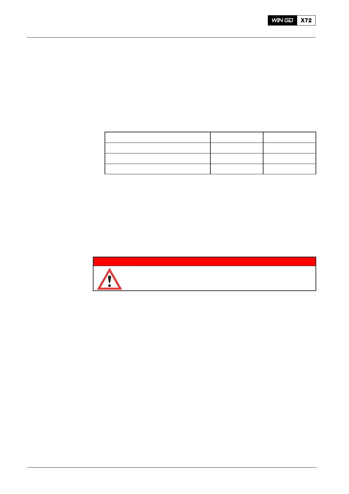
The values of resistors that are related to the the different remote controls are
given in Table 2.
Table 2: Resistor Values
Supplier Resistor Power
KONGSBERG Maritime 10 kOhm 0.6 W
NABTESCO 3.9 kOhm 0.6 W
SAM / Lyngsø 8.2 kOhm 0.6 W
4.4.1 Oil Mist Detector
1) To activate an alarm in the oil mist detection system, do steps a) to c):
a) Remove a plug from the junction box, or start the Test Menu in the control unit.
b) Connect the smoke test instrument (tool) to the test connection of a sensor.
c) Simulate oil mist to activate an alarm in the safety system.
4.4.2 Speed Pick-ups and Crank Angle Sensor Unit (TDC/BDC)
WARNING
Injury Hazard: Before you operate the turning gear, make sure
that no personnel are near the flywheel. Obey the data given in
0210−1 Safety Precautions and Warnings.
1) Do a check of the pick-ups for speed measurement and crank angle sensor unit
as follows:
a) Engage the turning gear.
b) Use the turning gear to turn the crankshaft.
c) Make sure that all LED on the speed pick-ups and the crank angle sensor unit
come on and go off when the crank angle mark and a flywheel tooth move
across the proximity sensor face.
d) Disengage the turning gear.
4.4.3 Level Switches
1) Do a check of the level switch in the condensate collectors as follows:
a) Manually operate the float switch to activate a high-level alarm.
2) Do a check of the level switch in the leakage oil return as follows:
b) Manually move the selector switch on the sensor to Min to activate a high-level
alarm.
2015-03
Engine Control