Operation6606−1/A1
Winterthur Gas & Diesel Ltd.
2/ 5
WDST BT
FW
PLANT
ENGINE
BT
22
5
6
7
21
20
19
15
8
10
11
12
13
12
43
14
AV
18
17
16
9
CA
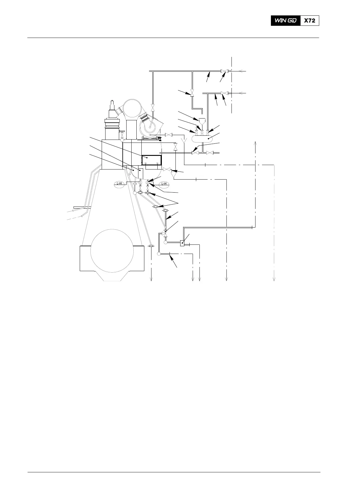
Fig. 1: Location of Wash-water System Parts
1 Fresh water supply pipe 16 Receiver
2 Ball valve 17 Water separator
3 Ball valve 18 Scavenge air cooler (SAC)
4 Compressed air supply pipe 19 Shut-off valve (vent)
5 Shut-off valve 20 Shut-off valve
6 Container 21 Funnel
7 Ball valve 22 Shut-off valve
8 SAC drain
9 Condensate collector
10 Throttle disc AV Vent
11 Condensate and wash-water drain BT Drain to bilge water tank
12 3-way ball valve CA Compressed air from board system 7.0 bar to 8.0 bar
13 Vent unit FW Fresh water 2.5 bar
14 Cleaning fluid and wash-water drain ST Drain to sludge water tank (oleiferous)
15 Level switch WD Drain to water drain tank
Operating Instructions and Cleaning
2015-03