Operation
6545−1/A1
Winterthur Gas & Diesel Ltd.
1/ 2
Auxiliary Blower and Switch Box
1. Auxiliary blower
1.1 General
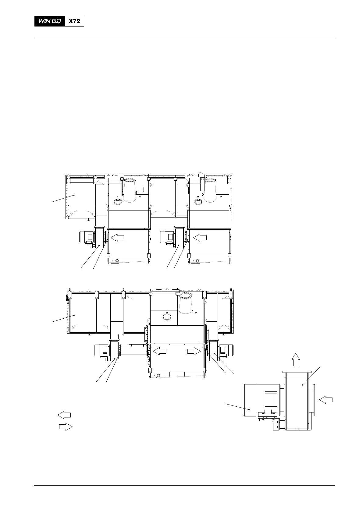
The electric motors (4, Fig. 1) operate the two auxiliary blowers (2), which are
installed on the scavenge air receiver (3). The auxiliary blowers supply air from the air
space through the duct (1) into the receiver space during the engine start and
operation at low load. Flaps prevent the back-flow of air to the scavenge air receiver
(see 6420-1 Scavenge Air Receiver).
Note: If the auxiliary blower does not operate for a long period, do the
procedure given in 0620−1 Prepare the Engine for a Long Shutdown
Period, paragraph 2.2 Procedures and Checks.
SS
4
2
WCH02242
2
3
2 11
WCH02243
PS
Design for Two
Turbochargers
3
2 1
2
1
Design for One
Turbocharger
WCH03717
= Direction of Airflow
Fig. 1: Location of Auxiliary Blowers
1 Duct 4 Electric motor
2 Auxiliary blower (left hand design) PS Pressure side
3 Receiver SS Suction side
2016−11
3