Operation4002−1/A1
Winterthur Gas & Diesel Ltd.
2/ 22
2. System Description
The engine control system on the X-engine is a modular system that has the items
that follow:
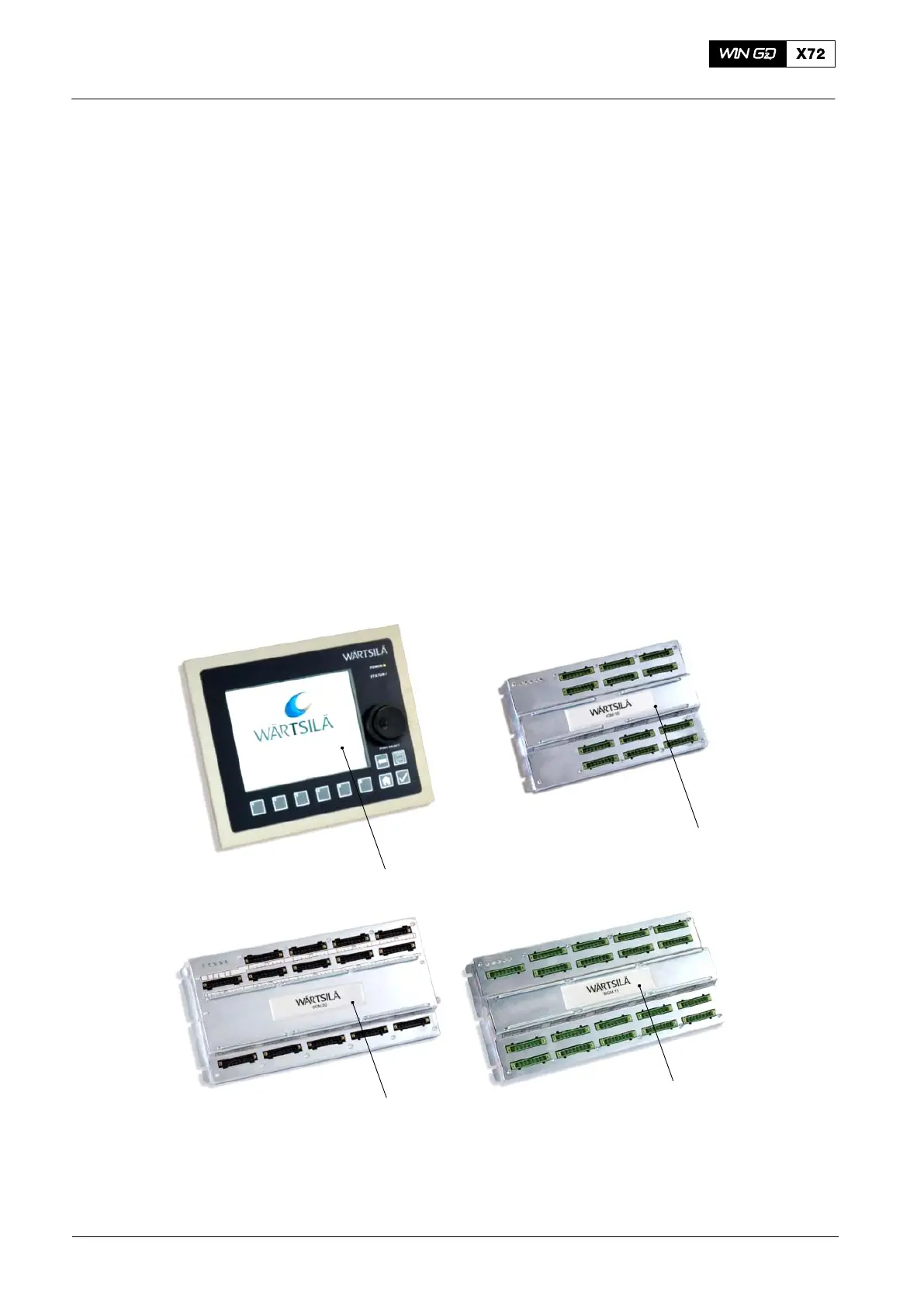
D Two local display units (LDU-20) (1, Fig. 1). One LDU-20 is installed at the local
maneuvering stand at the free end. The other LDU-20 is installed in the engine
control room (ECR). External control systems transmit data to the LDU-20. The
LDU-20 gives the operator a graphical user interface for access to data and
system adjustments. For more data, see 4002−2 Local Control Panel/ Local
Display Unit LDU-20, paragraph 3 LDU-20.
D One input/output module (IOM-10) (2), installed at the rail unit in the terminal
box E90. The IOM-10 has the engine control functions, e.g. exhaust waste gate
control and redundant sensor and actuator signals of the MCM-11.
D One cylinder control module (CCM-20) (3) for each cylinder, installed on the rail
unit in the terminal box E95. The CCM-20 has cylinder-related control functions.
The CCM-20 also has redundant global functions for engine control.
D One main control module (MCM-11) (4), installed at the rail unit in the terminal
box E25. External control systems transmit data to the MCM-11. The MCM-11
has functions for speed control and common engine functions (e.g. start valve
control).
Redundant CAN system busses connect all the modules (see paragraph 2.3).
1
3
4
2
WCH02935
Fig. 1: ECS Modules
1 Local display unit (LDU-20) 3 Cylinder control module (CCM-20)
2 Input output module (IOM-10) 4 Main control module (MCM-11)
2015-12
Engine Control System