Operation
4002−1/A1
Winterthur Gas & Diesel Ltd.
3/ 22
Speed
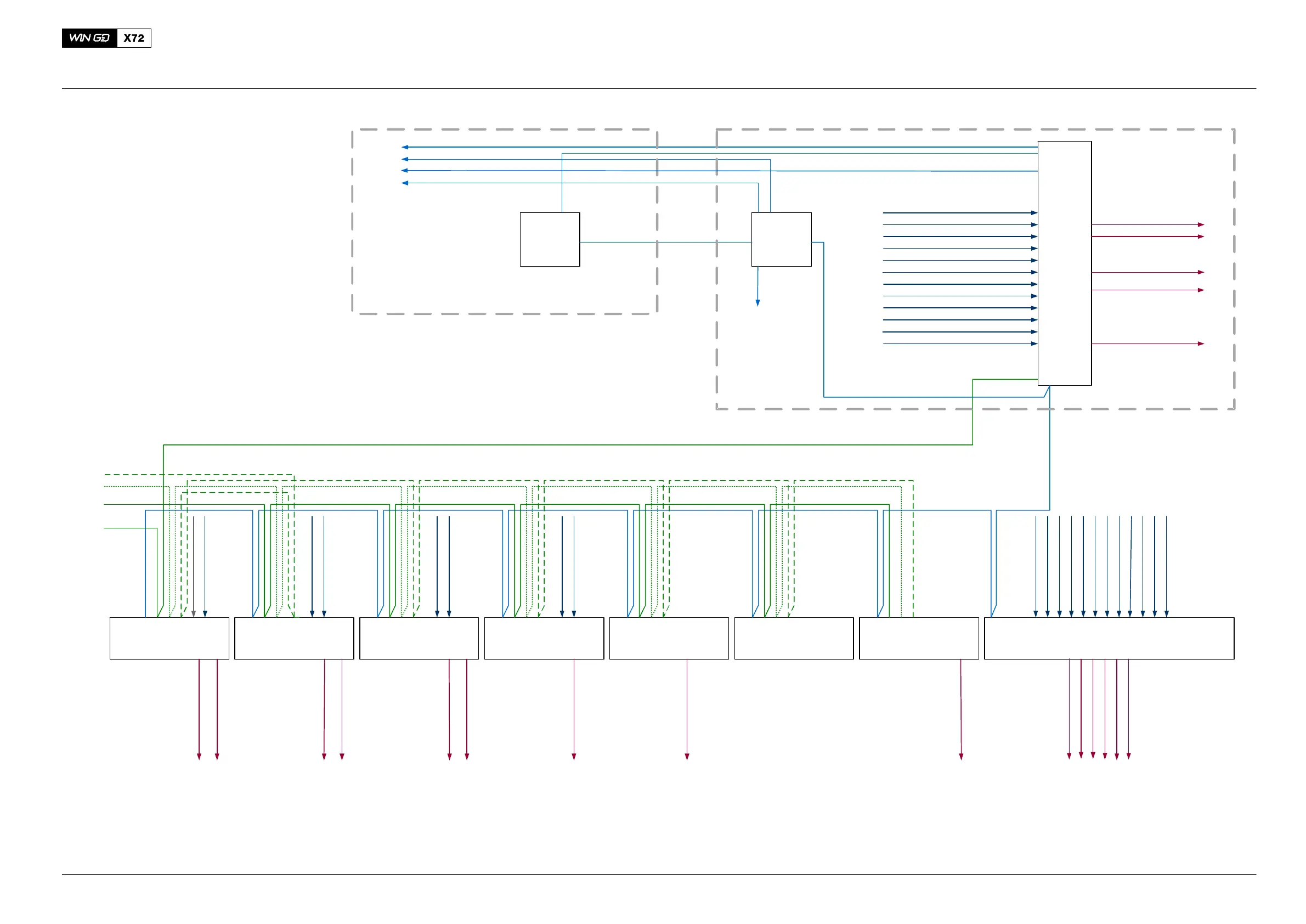
Color Codes:
Diesel
Gas
Bus
Power
WCH03159
CCM-20 A1
Cylinder #1
CCM-20 A2
Cylinder #2
CCM-20 A3
Cylinder #3
CCM-20 A4
Cylinder #4
CCM-20 A5
Cylinder #5
CCM-20 A6
Cylinder #6
IOM-10
LDU-20
LDU-20
(ECR)
CAN
To PCS
Common Start Vlv #1CV7013C
Aux Blow #1 Start
CY7031C
Fuel Press #1PT3461C
Servo Oil Press #1PT2071C
FuelPress #2
FuelPress. Supply UnitPT3421C
PT3462C
Servo Oil Press #2PT2072C
Air Spring Air PressPT4341C
Brng. OilPressPT2002C
FuelPump Act. #1
Supply Gear Wheel Sens. B+TDC
CV7231C
FuelPump Act. #2
Supply Gear Wheel Sens. C+BDC
CV7232C
ServOilPump#1 PCV
Supply Gear Wheel Sens. D
CV7221C
Serv OilPump #2 PCVCV7222C
UNITool
Ethernet
CAN
CAN
Fuell Pump Act. #3*
CV7233C
MCM-11
CCM-20 A7
Cylinder #7
Serv Oil Pump Act. #3*CV7223C
Supply Gear Wheel Sens. A
System Bus 1 + 2
System Bus 1 + 2
System Bus 1 + 2
Gear Sens. A+B
ST5131/32C
Gear Sens. C+D
ST5133/34C
TDC Sign.
ZS5123C
BDC Sign.
ZS5124C
Gear Wheel Sens. A+B
ST5131/32C
E25ECR
Note
Signals with an „*“ depend on
the number of cylinders and/or
number of TC
Inj. Lub Shut-off VlvCV7003C
To AMS
Power / TorqueJT5156C
Rail Unit
Ethernet
Modbus
Modbus
CY7036C
Aux Blow #1 Setp.**
Note
** = Only with E21 with
Frequency Converter
HFO Supply
XS3411C
Starting Air Press #1 Before Shutoff VlvPT4301C
Main Start Vlv Man. ClosedZS5018C
Turn. Gear diseng #1ZS5016C
Aux Blow #1 running
JS5031C
Ctrl. Air Press Inl.PT4421C
Scav Air Press #1 in Air Rec. #1PT4043C
TC Speed #1ST5201C
Waste Gate #1 closedZS5372C
Waste Gate #2 closedZS5373C
Waste Gate Pos.XI7077C
X-Head Brng. Oil Press. Supply
PT2021C
TC Speed #2*ST5202C
Scav Air Press #2PT4044C
Aux Blow #2 running
JS5032C
CylCool.Water PressPT1101C
Turn. Gear diseng #2PT5017C
Starting Air Press #2
PT4302C
PT4003C Barometric Press. B
PT4002C Barometric Press. A
TE4046C TCAirTempaft.Cooler B
TE4045C TCAirTempaft.Cooler A
TCAirTempbef.InletBTE4042C
TCAirTempbef.InletATE4041C
Waste Gate Ctrl. Vlv
CV7077C
WasteGateCtrl.Vlv#2CV7078C
CY7037C
Aux Blow #2 Setp.**
CY7032C Aux Blow #2 Start
Common Start Vlv #2
CV7014C
CV7076C
WasteGateCtrl.Vlv#1
Fig. 2: Schematic Diagram − Bus Routing Connections (without cylinder-related signals)
Engine Control System UNIC
2016−11