Operation
4002−1/A1
Winterthur Gas & Diesel Ltd.
13/ 22
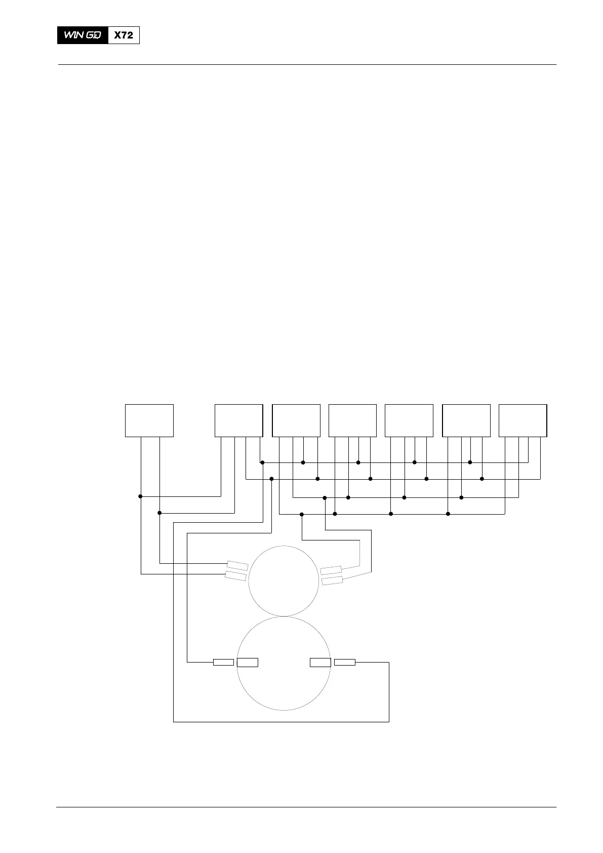
3.5 Engine Speed and Crank Angle Sensor
Four proximity sensors (A and B, C and D) are installed near the crankshaft gear
wheel (see Fig. 7). As the crankshaft gear wheel turns, the proximity sensors sense
the movement of the teeth and calculate the crankshaft position (see also
9223−1 Crank Angle Sensor Unit).
The inductive proximity sensors (speed pickups) A and B are connected to
CCM-20 Cyl. 1 and then looped to the MCM-11 (see Fig. 2).
The inductive proximity sensors (speed pickups) C and D are connected to
CCM-20 Cyl. 2 and then looped through to CCM-20 Cyl. n (see Fig. 2).
Additionally, one proximity sensor for TDC and one proximity sensor for BDC is
installed near the flywheel. These proximity sensors detect the reference marks
attached to the flywheel (see also 9223−1 Crank Angle Sensor Unit).
The crank angle is calculated incrementally by counting pulses (gearwheel teeth) from
the reference position to the current position in each CCM-20 individually.
The reference positions (TDC and BDC) are detected with separate sensors. The
reference points are the centers of the TDC and BDC marks.
To detect the sense of rotation there is always a pair of gear wheel sensors (A and B,
C and D). If one of the sensors fails the data (sense of rotation) is available on the
CANBus.
The reference sensor signals are used to synchronize the relative position signal to
the absolute crankshaft angle.
DATA FOR
6 CYLINDERS
CCM−20
Cyl. 1
CCM−20
Cyl. 2
CCM−20
Cyl. 3
CCM−20
Cyl. 4
CCM−20
Cyl. 5
CCM−20
Cyl. 6
Flywheel
Sensor
A and B
Crankshaft
Gear Wheel
Sensor
TDC
MCM−11
E25
Sensor
C and D
Sensor
BDC
Fig. 7: Crank Angle Sensors
Engine Control System
2015-12