Operation
0530−1/A1
Winterthur Gas & Diesel Ltd.
1/ 2
CCM-20 Failure
1. CCM-20 Failure
1.1 Identification
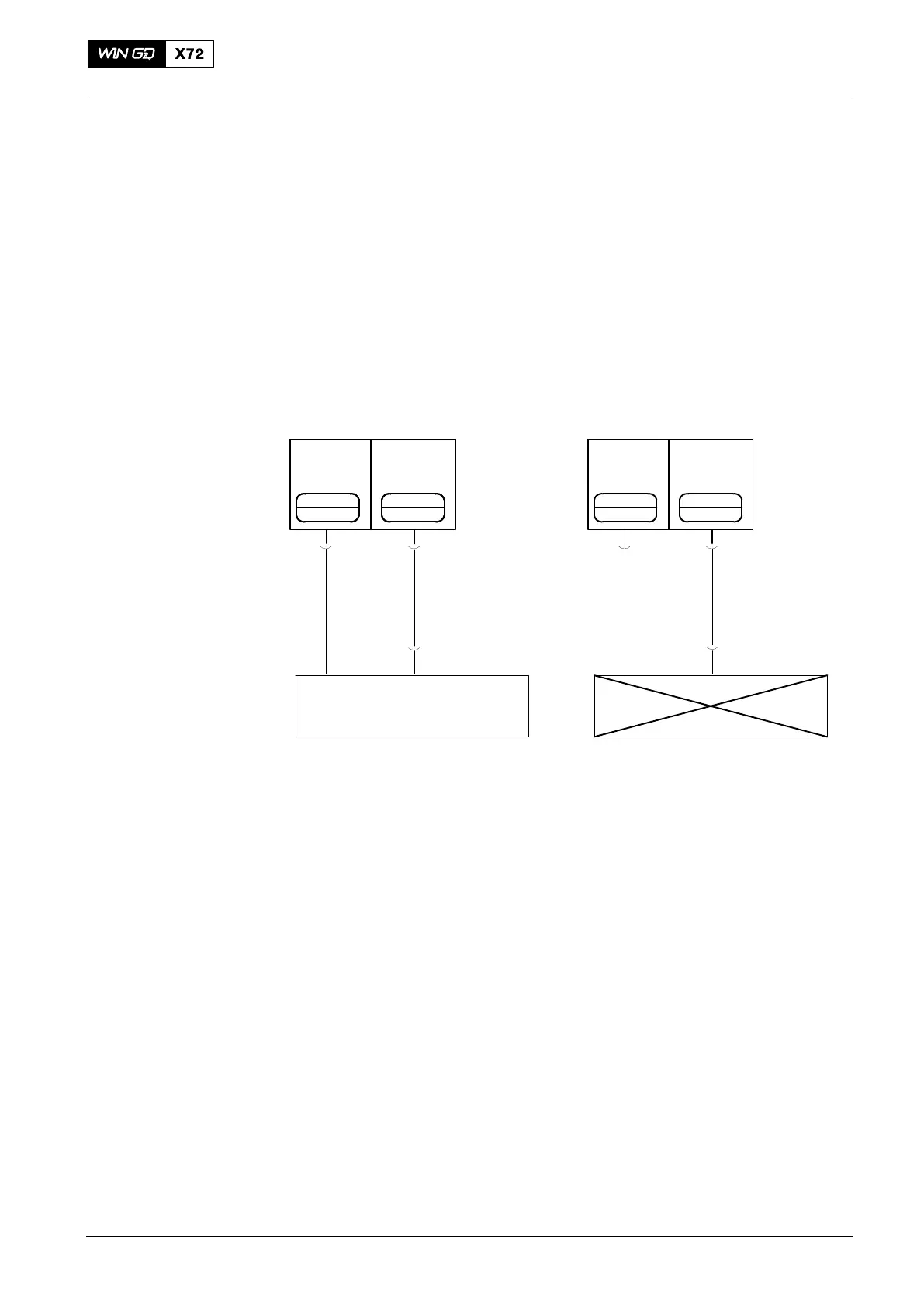
The alarm Module Fail CCM#X shows in the engine control system (ECS). Fig. 1
shows a schematic diagram of the CCM-20 in usual configuration.
1.2 Cause
The CCM-20 of cylinder X is defective, thus the related cylinder has no lubrication.
CYL. LUB.
OIL
PRESS.
CYL. LUB.
VALVE
COMMAND 1
PT
313YC
CV
713YC
CYL. LUB.
OIL
PRESS.
CYL. LUB.
VALVE
COMMAND 1
PT
313YC
CV
713YC
CYL. LUB.
OIL
PRESS.
CYL. LUB.
VALVE
COMMAND 1
PT CV
CYL. LUB.
OIL
PRESS.
CYL. LUB.
VALVE
COMMAND 1
PT
313XC
713XC
CCM−20
CYL. Y
Defective CCM−20
CYL. X
CYLINDER Y
A
Usual Cylinder Lubrication
CYLINDER X
No Cylinder Lubrication
BC
Fig. 1: Schematic Diagram − Usual Configuration
1.3 Procedure
If a CCM-20 has a failure, you use the terminal box (tool 94929) to bypass the
defective CCM-20 and give emergency lubrication to the related cylinder.
Do steps 1) to 7) to install the terminal box (see Fig. 1 and Fig. 2).
1) Attach the terminal box to the cylinder block near the applicable cylinder
lubrication pump. The terminal box has magnets installed in the base.
2) Disconnect the connection A (from the valve CV713YC) on the cylinder lube
pump on Cylinder Y.
3) Connect Socket A on the terminal box, to the connection A (valve CV713YC).
4) Connect Socket B on the terminal box to to the connection B (valve CV713YC) of
the cylinder lube pump on Cylinder Y.
5) Disconnect the connection C (from the valve CV713XC) on Cylinder X.
6) Connect Socket C on the terminal box to the connection C (valve CV713XC) of
the cylinder lube pump of Cylinder X.
Note: The piston that has emergency lubrication will operate, but will not fire.
7) If the defective CCM-20 operates correctly again, disconnect the terminal box
and connect all valves to their related CCM-20 modules.
2015-03
Operation during Unusual Conditions