Operation
4605−1/A1
Winterthur Gas & Diesel Ltd.
1/ 3
Control Air Supply
1. General
The compressed air necessary for the air springs in the exhaust valves and the
turning gear interlock comes from the control air board supply. The air must be clean
and dry to prevent blockages in the control units.
If the control air board supply system becomes defective, a decreased quantity of
compressed air will come from the starting air system.
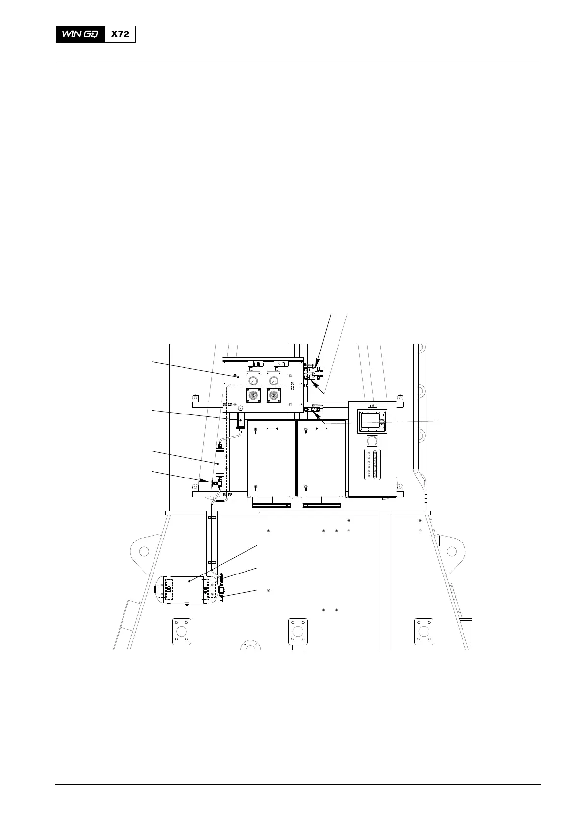
The shut-off valves, pressure reducing valve, filters etc. that are necessary to supply
air to the different units are shown in the control air supply unit A (see Fig. 1, Fig. 2
and Fig. 3).
The alpha-numeric titles (e.g. 35-36HB) used to identify the parts in the illustrations
are the same as those in the Control Diagram (4003−2).
1 2
3
6
5
4
8
7
9
10
WCH03200
Fig. 1: Location of Control Air Supply
1 3/2−way valve 35-36HB (control air) 6 Air tank
2 3/2−way valve 35-36HC 7 Needle valve
3 3/2−way valve 35-36HA 8 Bottle
4 Pressure transmitter PT4421C 9 Filter 35-351HA
5 Pressure transmitter PT4421A 10 Control air supply unit A
2015−03