Operation
8825−1/A1
Winterthur Gas & Diesel Ltd.
1/ 6
Electrical Trace Heating System
1. General 1..........................................................
2. Electrical Trace Heating 1...........................................
2.1 Power Consumption Values 2..................................
2.2 Usual Operation 2.............................................
2.3 Operation Modes 2............................................
2.4 MDO / HFO Supply Status (E88 to ECS) 2.......................
2.5 Alarms from E88 to the Alarm and Monitoring System 3.........
2.6 230 VAC Emergency Switchboard Supply to E88 3..............
1. General
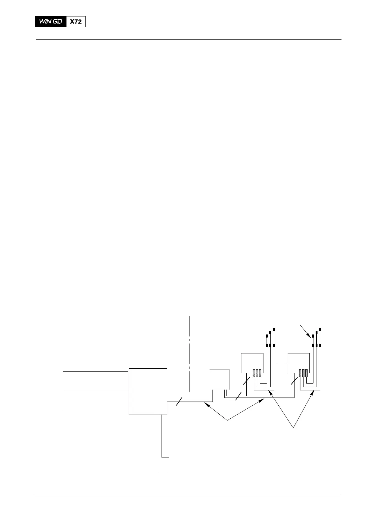
The main and emergency switchboards supply 230 VAC single phase (230 VAC) to
the control box E88 (see Fig. 1 and Fig. 2). The control box E88 is installed in the
engine room near the engine.
The control box E88 also supplies 24 VDC to the XS3411C HFO supply and to the
temperature element TE3411C.
2. Electrical Trace Heating
The control box E88 supplies electrical power to the terminal box E89. The terminal
box E89 supplies power to each connection box E89.01 to E89.0X (see Fig. 1).
The connection boxes E89.01 to E89.0X supply power to the trace heating cables for
each fuel injection pipe (see Fig. 2 and Fig. 3).
The electrical trace heating system heats the fuel injection pipes to the target
temperature of 130C 10% and keeps this temperature stable.
The electrical heating cables are the self-control type i.e. the electrical current
absorbed decreases in relation to an increase in temperature until a stable condition
occurs. The power consumption is related to the temperature of the electrical heating
cables.
When the heating cable is at the target temperature, the heating cable stays on, but
at the lowest power consumption.
E88
E89
E89.01 E89.0x
230 VAC
Main Supply
230 VAC
Emergency Supply
XS3463A
Alarm System
PLANT ENGINE
N
N
XS3411C HFO Supply
TE3411C
Power Supply Cables
N = No. of Cylinder
Power Supply Cables
T_Max = 145°C
Cyl 1 Cyl n
1
1
WCH02294
Electric heating cables on fuel injection pip
Fig. 1: Schematic diagram − Electrical heating system
2015-03