Operation6545−1/A1
Winterthur Gas & Diesel Ltd.
2/ 2
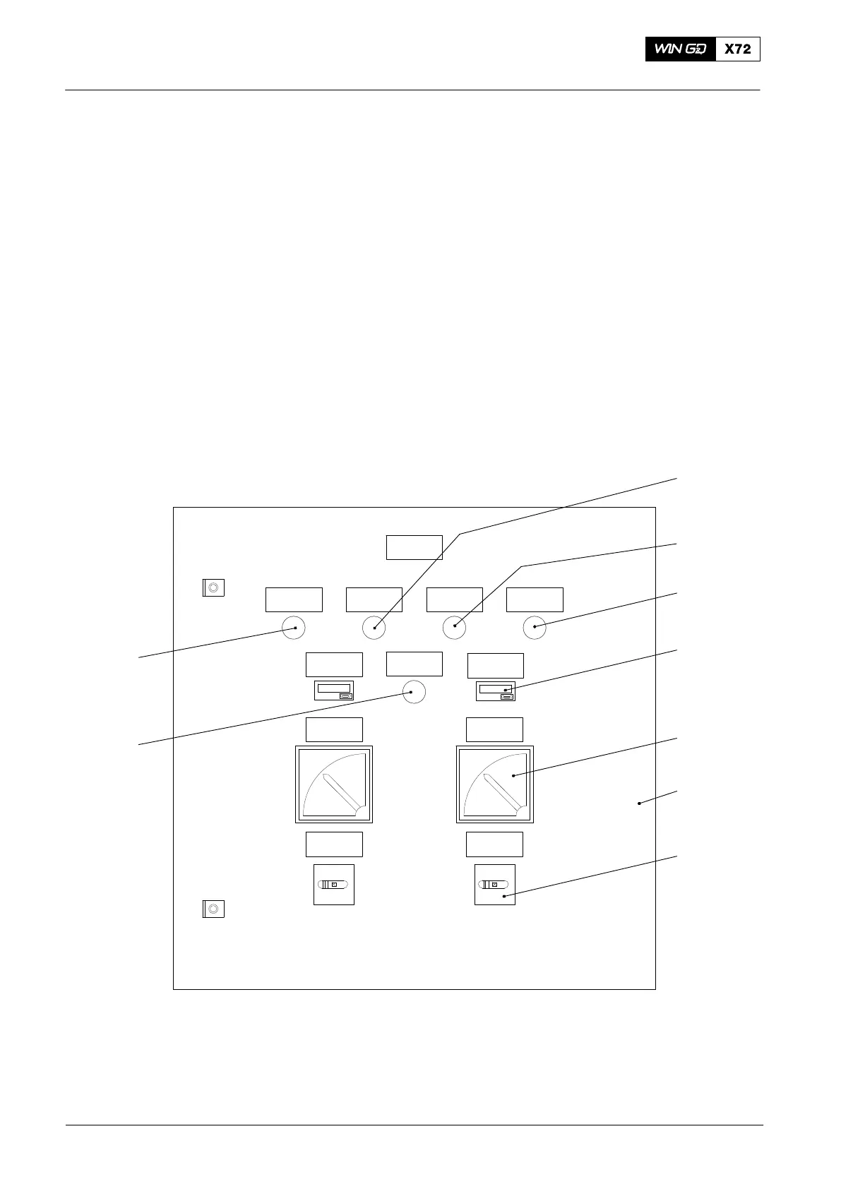
2. Switch box
2.1 General
The engine builder supplies an electrical switch box (5, Fig. 2) for each auxiliary
blower.
2.2 Function
During the engine start procedure, the first auxiliary blower starts immediately. After
approximately two to three seconds, the other auxiliary blower starts.
When the turbocharger produces sufficient pressure in the scavenge air receiver, the
auxiliary blowers stop.
If the scavenge air pressure decreases below the minimum pressure necessary, the
auxiliary blowers operate as given above (for more data, see 4003−1, paragraph 4.5
Auxiliary Blowers).
Note: For emergency operation, if both scavenge air pressure transmitters
(PT4043C and PT4044C) become defective, you can control the auxiliary
blowers manually.
−H1.3
−H2.3
−H1.2−H2.2 −H2.4
E21
−P1 −P2
−Q2.1−Q1.1
WCH02329
−H1.4
−H1.1
1
2
1
3
4
5
6
7
8
Fig. 2: Switch Box
1 Overload indicator 5 Switch box
2 In operation indicator 6 Hour counter
3 Main switch 7 Control voltage indicator
4 Ampere meter 8 In operation indicator
2015-12
3
Auxiliary Blower and Switch Box