Maintenance
1132−2/A1
Winterthur Gas & Diesel Ltd.
5/ 15
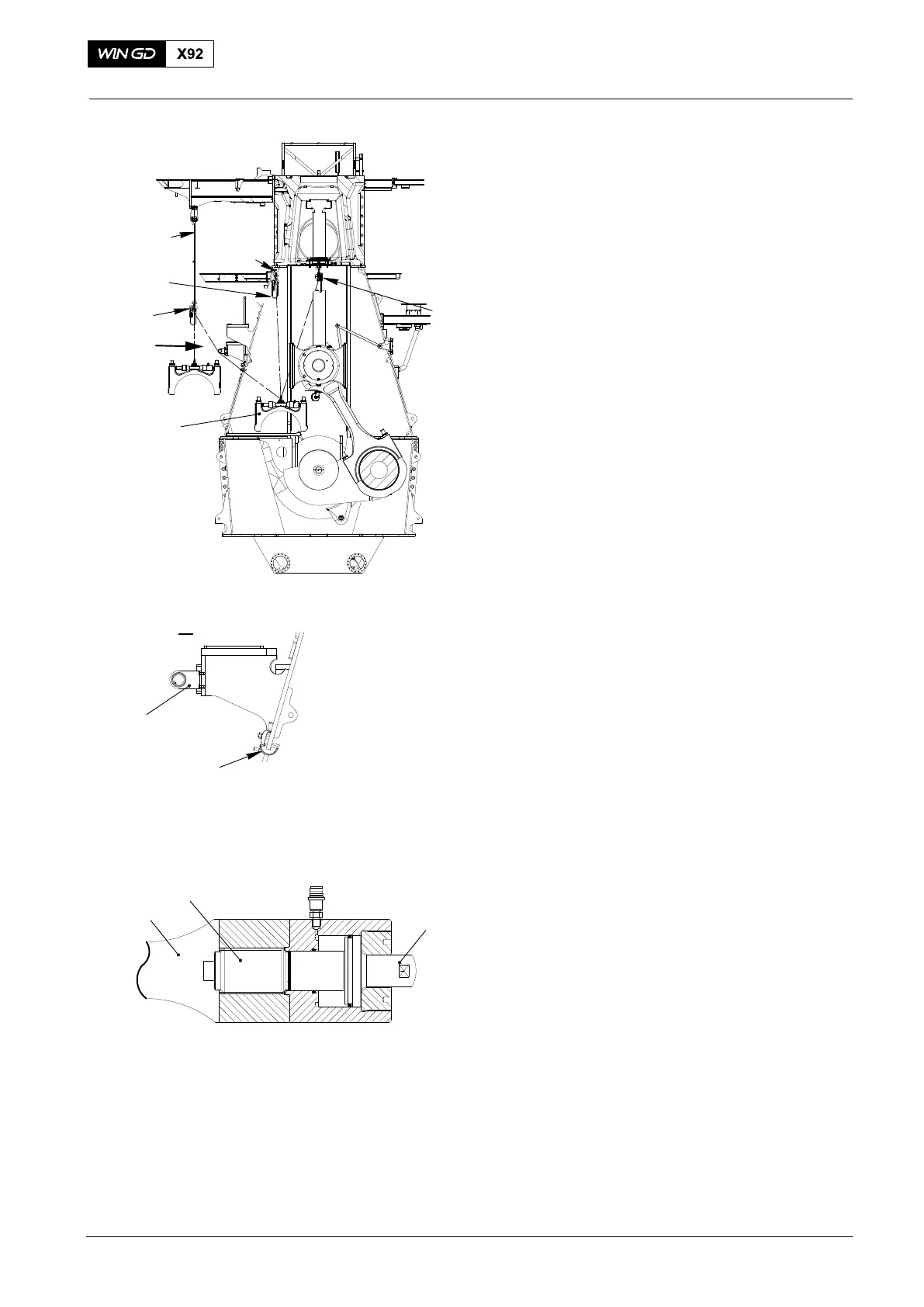
30) Attach the sling 94039-015 to the
gallery (Fig. 7).
31) Attach the chain block 94017-029 (H3)
to the sling 94039-015.
32) Attach deviation pipe 94117B and
94117C to the column, see view I.
33) Attach the chain block 94017-028 (H2)
with shackle 94019P to the column.
34) Use the chain blocks (H2) and (H4) to
move the bearing cover (1) to the fuel
side until the bearing cover hangs
vertically on chain block H2.
35) Attach the hook of chain block (H3) to
the bearing cover (1).
36) Disconnect the chain block (H4) from
the bearing cover (1).
37) Use the chain blocks (H2, H3) to move
the bearing cover (1) out of the column.
38) When the bearing cover (1) hangs
vertically, remove the spur geared
chain block (H2).
39) Lower the bearing cover (1) on to a
wooden underlay.
40) Connect the thrust device (94110) to
the HP oil pump 94931.
41) Apply 1040 bar pressure to the thrust
device.
42) Turn screw (5) back.
43) Slowly release the pressure to zero in
the thrust device (94110) refer to
9403−2..
44) Insert the piston (3) and remove the
thrust device 94110.
Note: To remove the main bearing cover
No. 1, refer to paragraph 3.
Note: Keep the spur-geared chain blocks
(H2, H3, and H4) in position on the
sling 94039-015, and the column.
2015
Main Bearing − Removal and Installation
Fig. 7
94039−015
H3
H4
H2
1
WCH03014
I
I
94117B
94117C
94019P
WCH03014
5
3
94110
THRUST DEVICE 94110