Maintenance3103−1/A1
Winterthur Gas & Diesel Ltd.
2/ 3
Note: Step 1) is applicable only for a cold engine. If the engine has usual
operation temperature, continue from step 2).
1) Make sure that the tank heater and lubricating oil separator are set to off a minimum
of eight hours.
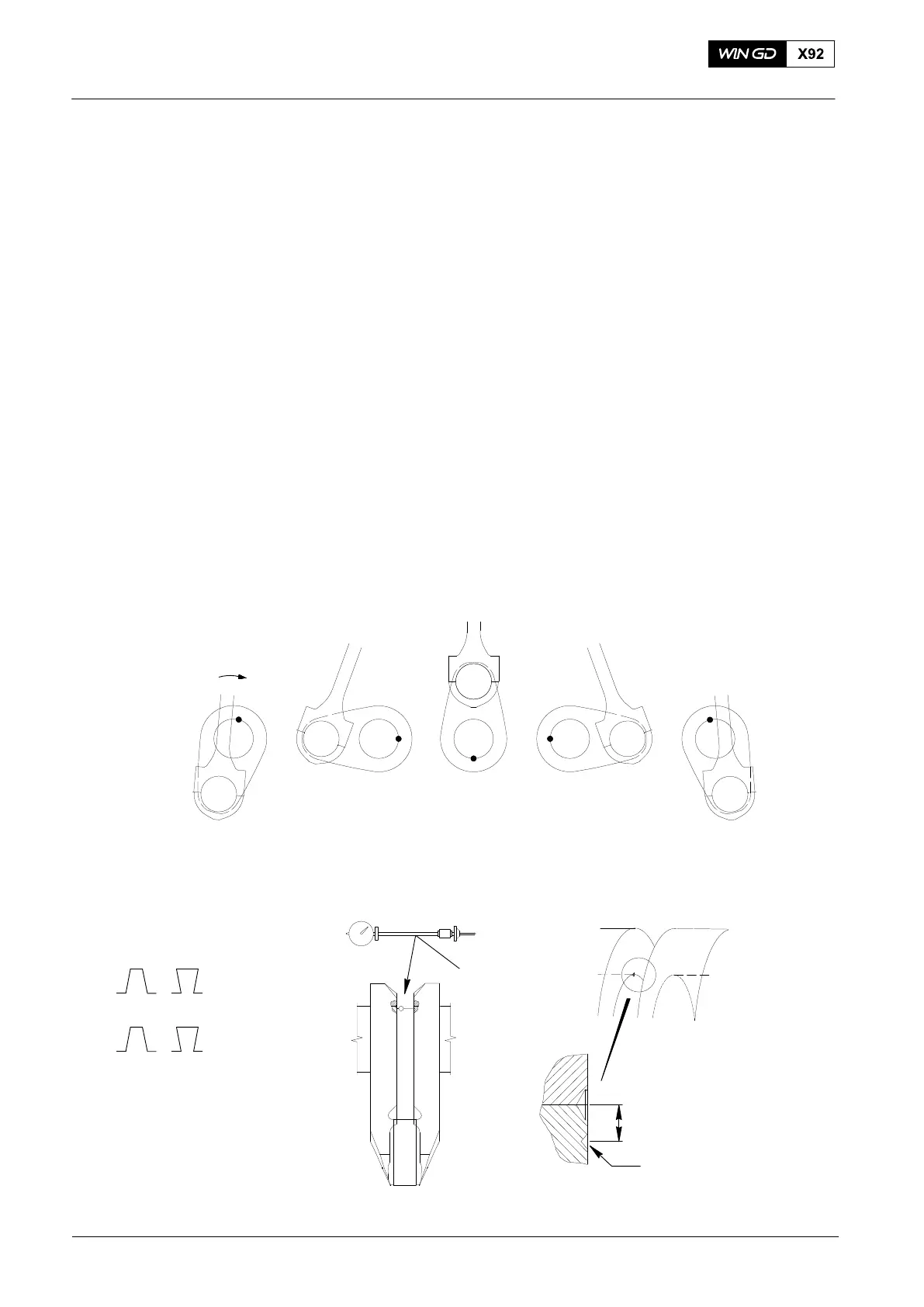
2) Use the turning gear to move the crank into the BDC 1st position (see Fig. 2).
3) Attach the dial gauge 94305 to the connecting rod. Make sure that the dial gauge
goes into the center punch marks.
4) Turn the rod of the dial gauge to apply tension.
5) Set the dial gauge to zero. The dial gage must not have a difference of more than
0.01 mm.
6) Use the turning gear to move the crank to each position shown. At each position,
record the indications on the dial gauge.
Note: The change in the distance between the crank webs can be read from the
dial gauge. The smaller the difference, the better the crankshaft is
aligned.
7) If the difference between the two BDC positions is more than 0.05 mm, you must do
the check again.
CRANK DEFLECTION
SIGN ON DIAL GAGE
+ −
− +
OR
VIEW FROM
DRIVING END
CLOCKWISE
DIRECTION
94305
Approximately.
18 mm
Center Punch Mark for
Dial Gauge 94305
Fig. 2
BDC 1st Position
FUEL SIDE
TDC
EXHAUST SIDE
BDC 2nd Position
2015
Measuring Crank Deflection