Maintenance
3103−1/A1
Winterthur Gas & Diesel Ltd.
3/ 3
4. Date Evaluation
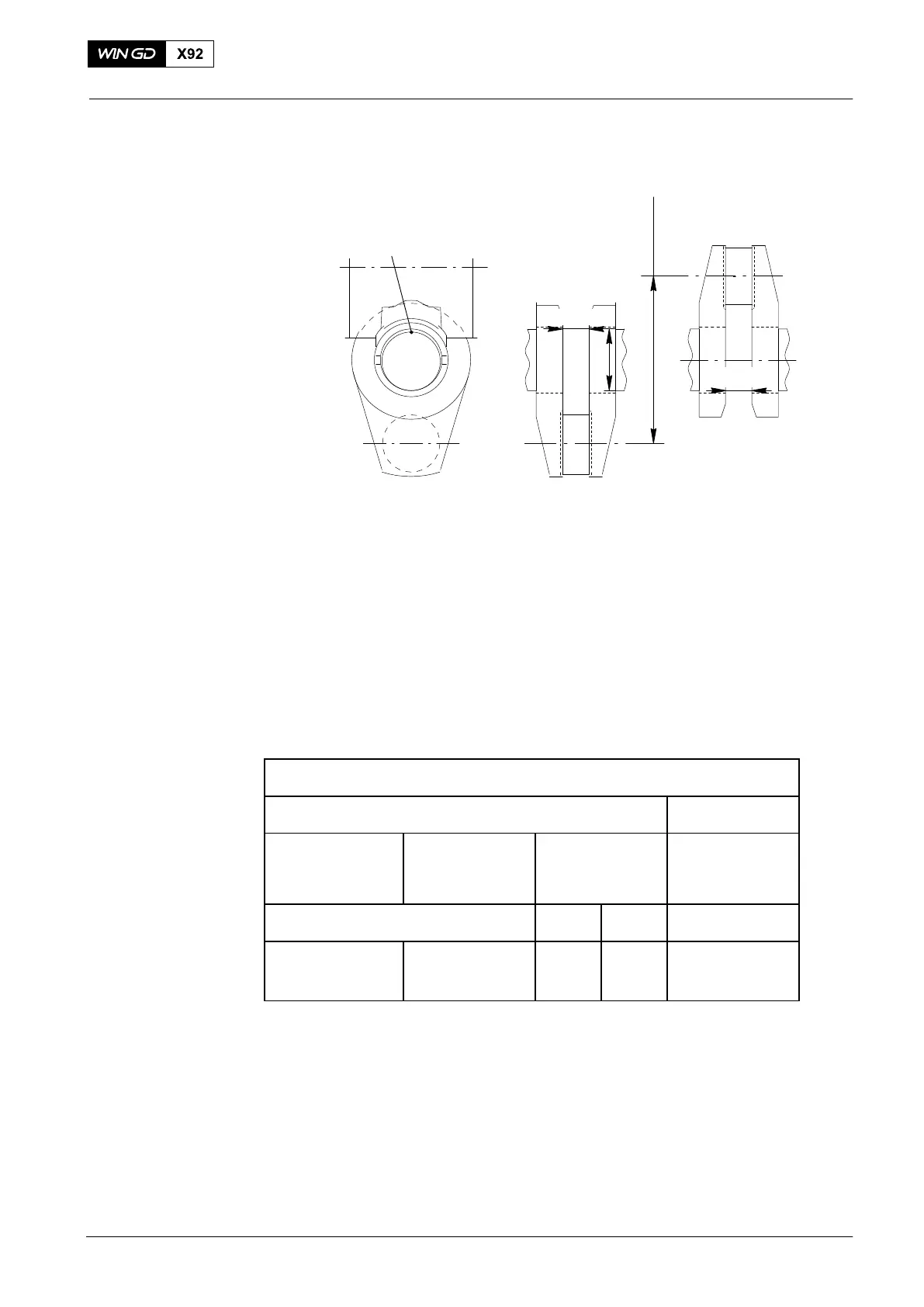
STROKE
D
94305
nBDC
nTDC
Fig. 3
The difference between the indicated values shows the crank deflection during one
full turn (Fig. 2).
Where values are measured, which are above the maximum permitted limits, you
must find the cause (e.g. defective main bearing, engine stay changed because hull
deformation, loose hold-down bolts, defective propeller shaft bearings, equipment
94305 etc).
The limits are applicable for all conditions of ship operation after delivery i.e.:
D The draught and trim of the ship are in the limits for usual operation.
D The engine is hot or cold.
Table 1: Deflection Limits
Usual Ship Operation: Crank-web Deflection Limits (mm)
Vertical Horizontal
Cylinder No. 1
(Driving End)
Cylinder No. 2
to Last but One
cylinder
Last Cylinder
(Free End)
All Cylinders
Note
1) Note
2)
1.08
−1.08
0.76
−0.76
0.76
−0.76
0.76
−1.08
0.35
−0.35
1) For engines without a torsional vibration damper, front disc or free end Power Take
Off.
2) For engine with a torsional vibration damper, front disc or free end Power Take Off.
Speak to Wärtsilä Switzerland, if the last data is more than the limits given in the table
above.
2015
Measuring Crank Deflection