Maintenance
3303−3/A1
Winterthur Gas & Diesel Ltd.
5/ 8
5. Bearing Shell − Installation
1) Clean the seating surface of the bearing shell (2, Fig. 6).
2) Put oil on the surface of the bearing shell as follows:
a) If you start the engine immediately after completion of this procedure, use only
bearing oil.
b) If the engine has stopped for some days, use a mixture of high-viscosity oil
(steam engine cylinder oil, ISO VG 1000/1500) and bearing oil. The ratio is two
thirds ISO VG 1000/1500 to one third bearing oil.
Note: A list of suppliers for ISO VG 1000/1500 high viscosity oils is given in
Table 1.
3) Clean the seating surface of the connecting rod and make sure that there is no
damage.
4) Make sure that the surface of crosshead pin is in a satisfactory condition.
5) Install the brackets 94326A on the bearing shell (2, Fig. 6) with the lugs towards the
inside, see detail I.
6) Attach the chain 94325 to the brackets 94326A.
7) Lift, lower and push the bearing shell with chain block H6 and manual ratchet H4 into
position of the connecting rod (1) as shown in Fig. 6.
8) Install the two screws (3, Fig. 6) to the bearing shell (2).
9) Remove the chain 94325 and the
brackets 94326A.
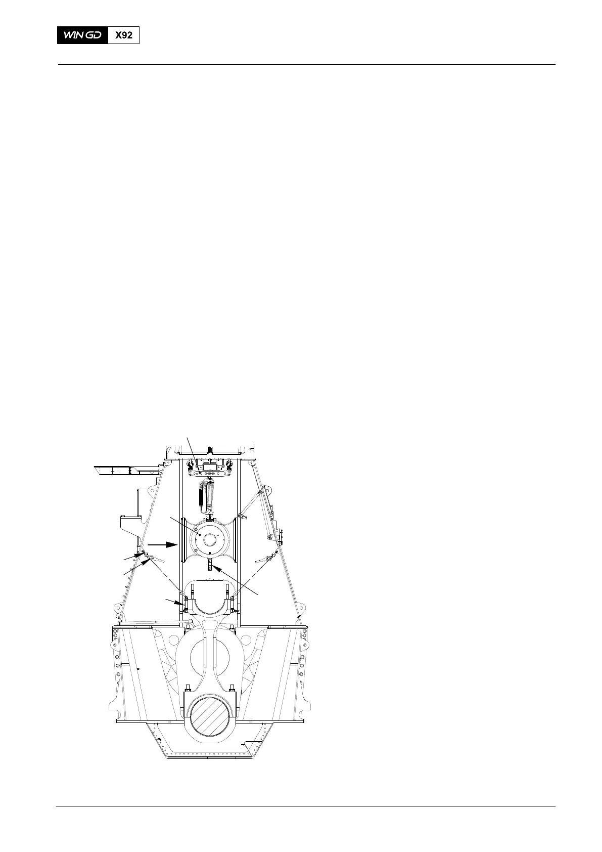
10) Attach the manual ratchet (H4, Fig. 7)
to the lifting tool 94337.
11) Use the manual ratchets (H4) and (H3)
to move the connecting rod to the
center position below the crosshead.
12) Install the platform 94143.
13) Lift the crosshead (2) approx. 300mm
with chain block (5) and tighten manual
ratchets (H1, H2, Fig. 5).
14) Remove the two supports 94322.
15) Operate the chain blocks (H5, H1, H2)
to carefully lower the crosshead into
position on the connecting rod.
16) Connect the toggle lever (1) to the
connection piece.
2015
Top End Bearing − Removal, Inspection Installation
94322B
94016−015
94322
H5
2
Fig. 7
94019L
94337
H4
H3
I
WCH03017