Maintenance
3303−4/A1
Winterthur Gas & Diesel Ltd.
5/ 5
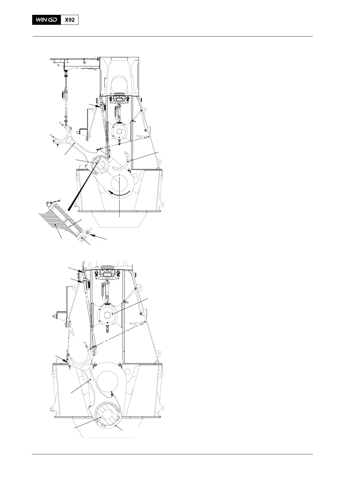
6) Carefully move the lower end of the
connecting rod (1) inside the column.
7) Attach hook of manual ratchet (H2) to
the upper end of rod (3, Fig. 7).
8) Use chain block (H3) and manual
ratchet (H2) to pull the connecting rod
carefully onto the crank pin (2).
9) Disconnect hook of chain block (H3)
from connecting rod.
10) Remove bolt (5) and connecting
Element (94334A).
11) Use suitable lifting tools to install
bracket 94334 to the rods (3).
12) Tighten bolts (5).
13) Use the turning gear to turn the crank
pin (2) clockwise and simultaniusly
guide the upper part of the connecting
rod through the column door.
When the upper part of the connecting rod
is passing the door, take over the weight
from chain block (H4) to (H3), see Fig. 3.
14) Use the turning gear to turn the crank
pin (2) clockwise to BDC, see Fig. 9.
15) Disconnect chain block (H3) from
connecting rod (1).
16) Use manual ratchets (H1) and (H2) to
move the connecting rod into vertical
position.
17) Lower and attach the crosshead (3) to
the connecting rod, refer to 3303−3,
paragraph 5.
18) Use the turning gear to turn the crank
pin (2) to near TDC.
19) Attach the hooks of manual ratchets
(H1) and (H2) to the lugs of bracket
94334, see Fig. 1.
20) Remove bracket 94334 completely.
4. Completion
1) Install bottom end bearing cover, refer
to 3303−2, paragraph 8.
2) Install the platform, (see 3303−1).
3) Attach the crosshead to the piston rod
foot, refer to 3303−3, paragraph 6.
4) Make sure that all tools and equipment
are removed from the area.
2015
Removal and Installation
H4
94334
1
3
H3
H2
94334A
5
Fig. 8
1
2
FUEL SIDE
Fig. 9
H2
94019P
WCH03037
H1
94017−045
H3
94337
94016−015
1
2
3
94334