Maintenance
5552−1/A1
Winterthur Gas & Diesel Ltd.
3/ 6
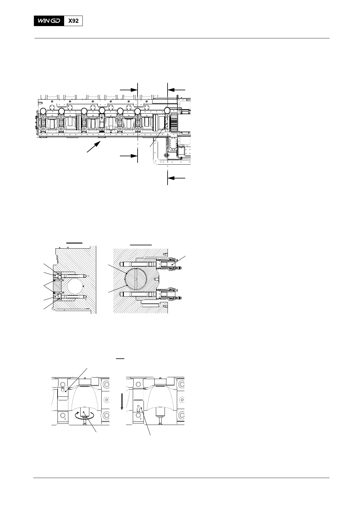
2. Bearing Shells −
Removal
1) Loosen the two Allen screws (2, Fig. 3)
and remove the filling piece (1) from
bearing cover No.2.
2) Use the pre-tensioning jacks (94557) to
loosen the round nuts (4) of the bearing
covers No.2, to No.7, refer to 9403−4.
3) Remove the round nuts (4) and the
bearing covers No.2 to No.7.
4) Put the screwjack (94567B) in position
under the cam.
5) Turn the screwjack (94567B) to lift the
camshaft between 0.05 mm and
0.15 mm.
6) Put the assembly template (94567) in
position on the top bearing shell (5) of
bearing No.5.
7) Use the assembly template (94567) to
turn the top and bottom bearing shells
(5, 6) 90° .
Note: If you cannot turn the bearing
shells, adjust the screwjack
(94567B) again.
8) Hold the top bearing shell (5), then
remove the assembly template
(94567).
9) Put marks on the top bearing shells to
identify their positions. This will help
you when you install the bearing shells.
10) Remove the top bearing shell (5).
11) Do step 4) to step 10) to remove the
remaining top bearing shells at bearing
covers No.3 to No.5.
2015
94567B
94567A
WCH02385
III
94567A
Fig. 3
3
3
4
4
2
I - I
II - II
94557
6
5
I
I
II
II
3
4
6
5
2
78
WCH02961
WCH02961
WCH02961
III
1
Camshaft and Bearing Shells − Removal and Installation