Maintenance
5552−1/A1
Winterthur Gas & Diesel Ltd.
5/ 6
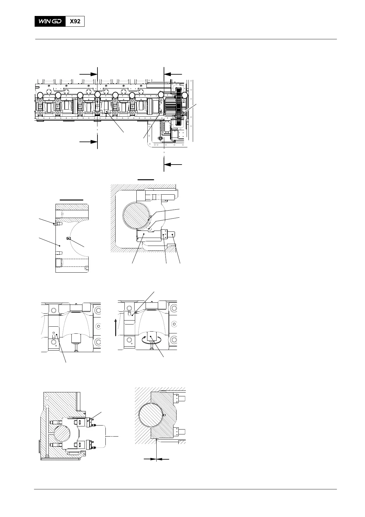
7) Put the screwjack (94567B, Fig. 5) in
position.
8) Turn the screwjack (94567B) to lift the
camshaft between 0.05 mm and
0.15 mm.
9) Put the assembly template (94567A) on
the bottom elastic bolt (7).
10) Put the round nut (8) on the elastic bolt
(7). Tighten the round nut with your
hand.
11) Put the top bearing shell (6) in position
on the camshaft.
12) Put the assembly template (94567) in
position on the bottom half of the top
bearing shell. Use the assembly
template (94567A) to help you get the
bearing shell in the center.
13) Use the assembly template (94567) to
turn the bearing shells (7, 8 Fig. 4)
90°upwards .
14) Make sure that the semicircular slots of
the two bearing shells (7, 8) are in a
horizontal position.
15) Remove the assembly templates 94567
and 94567A.
16) Remove the holder (94566A or
94566B).
17) Make sure that the pin (3, Fig. 5 is in
the bearing cover (4).
18) Attach the bearing cover (4).
19) Put the round nuts (8) on the elastic
bolts (7). Tighten the round nuts with
your hand.
20) Do the steps 1) to 19) for the remaining
bearing shells.
21) Remove the two supports (94566).
22) Put the bearing cover (4) that has the
dowel pin (5) on to position No. 3.
23) Install the tool (94557) on to the elastic
bolts (7) (see 9403−4).
24) Tighten the round nuts (8) to the value
specified in 9403−4.
25) Make sure that there is no clearance at
(X).
2015
Camshaft and Bearing Shells − Removal and Installation
6
94567A
94567
8
7
I - I
94567B
94567
WCH02385
94567
94557
X
II - II
5
4
3
Fig. 5
II
II
I
I
3
4
6
5
2
78
WCH02961
94567B
2
1
1