Maintenance5556−1/A1
Winterthur Gas & Diesel Ltd.
16/ 18
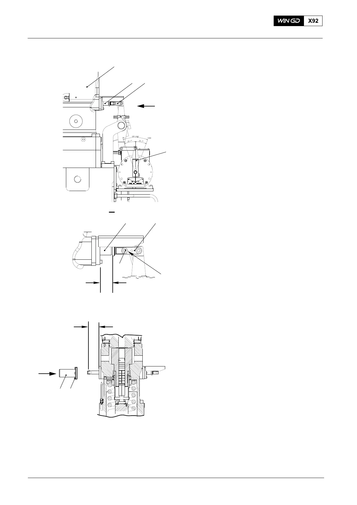
15) Make sure the connecting link (3, Fig.
26) moves freely.
16) Apply Molykote paste G to the
connecting link (3).
17) Connect the connecting link (3) to the
toothed rack (2) with the screw (8) and
a new self-locking nut (9).
18) Move the the toothed (2) rack to the
middle position as shown. Make sure
that there is 48 mm at each end of the
the toothed rack.
19) Make sure that the indicator on the
actuator shows 50% fuel.
20) Attach the cover (8) to the fuel pump
with the six screws (7).
21) Torque the six screws to 20 Nm.
Fuel Pump: Disassemble, Assemble
2015
Fig. 26
WCH03055
2
4
1
3
I
48 mm
6
2 3
I
5
48 mm
8 7
WCH03052