Maintenance6606−1/A1
Winterthur Gas & Diesel Ltd.
6/ 8
4. Installation (SAC at
Driving End)
1) Make sure that all the surfaces of the
SAC (1, Fig. 7) and the related
surfaces in the receiver are clean and
have no damage.
2) Apply a layer of silicon compound to
each side of the SAC (1) and the
related surfaces in the housing in the
receiver.
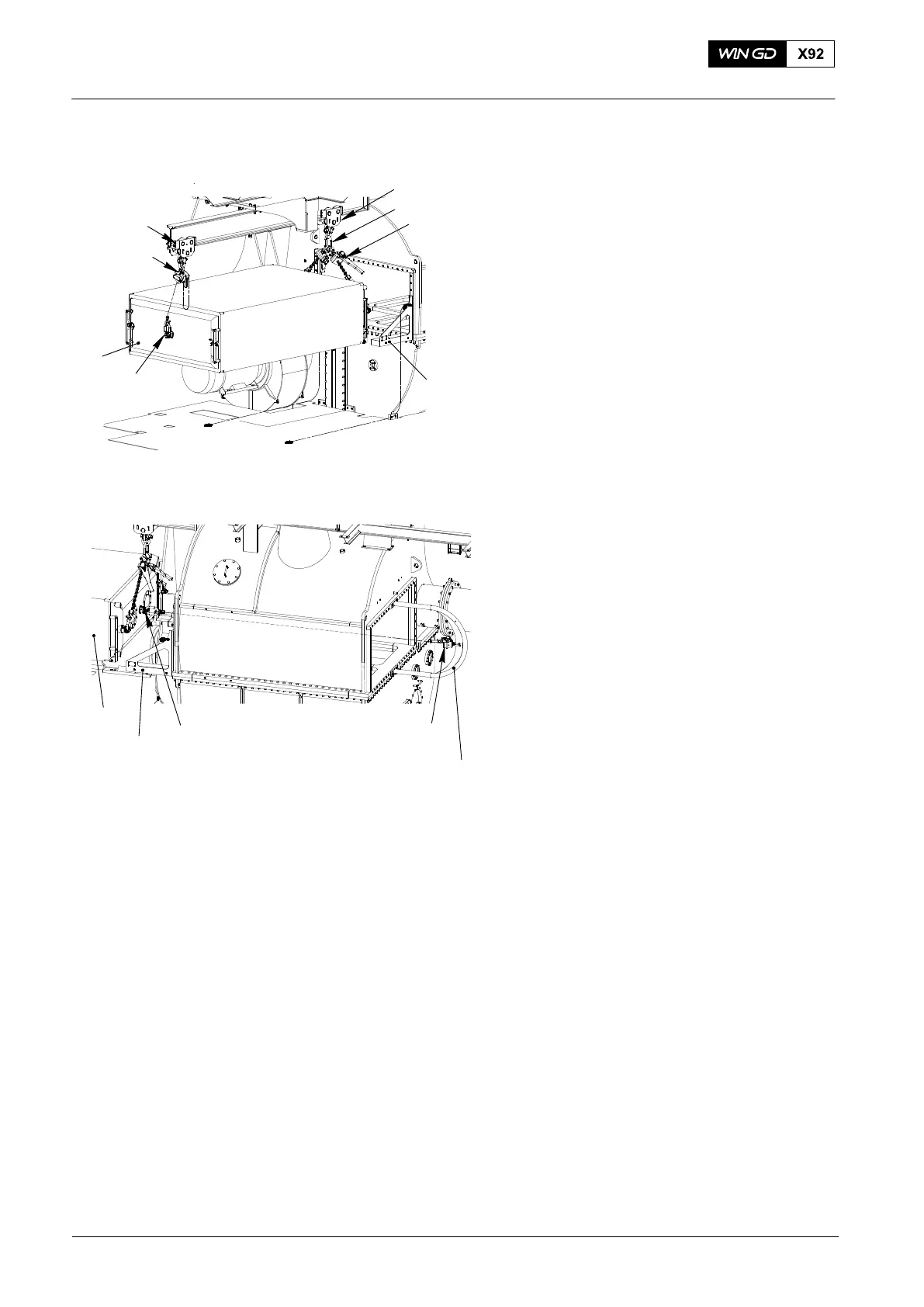
3) Use the tools that follow to move the
SAC (1) into position, see Fig. 7:
D Engine room crane
D Two trolleys 94015F
D Two Manual ratchets 94016-015
with ring 94666A and shackle
94019L
D Spur geared chain block
94017-028 with shackle 94019L
D Four Lugs 94048−M42.
4) Attach the support 94663I to the
receiver as shown in, Fig. 8.
5) Attach the rollers (2) to the SAC (1).
6) Attach the lug 94048−M42 to the center
location on the SAC (1).
7) Attach the manual ratchet 94016−003
to the support 94663I and center lug
9408−M42 on the SAC (1).
8) Operate the manual ratchet 94016−003
to move the SAC (1) on to the left and
right supports 94663A/B.
9) Remove the two manual ratchets
94016−015 from the rear of SAC.
10) Operate the manual ratchet 94016−003
to move the SAC (1) fully into into the
receiver (see Fig. 8).
11) Remove the two rollers (1) from the
free end of the SAC.
12) Install the two rollers (1, Fig. 9) to the
driving end of the SAC.
Scavenge Air Cooler: Removal and Installation
2015
Fig. 7
Fig. 8
94016−003
9408−M42
94663I
1
94015F
94663A/B
1
WCH02970
94017−028
4048−M42
94015F
94666A
94016−015
94663A/B
WCH02970