January 2010
4-107
Phaser 7760 Color Laser Printer
ADJ 9.14
Repairs and Adjustments
Revised
ADJ 9.14 RegiCon #4 Coarse Skew Adjustment
Procedure
1. Enter the hidden Service Menu: Printer Menu > Troubleshooting > Service Tools >
Printer Status Page > hold the Up and Down buttons simultaneously > RegiCon Setup
Cycle > OK.
NOTE: The first time any RegiCon test is requested, the pages used to perform the test
must be created, so there is a short delay. During this time the Control Panel displays Pro-
cessing Data - Please Wait.
2. Select Do #4: Coarse Skew Setup and press OK. The Control Panel displays: Testing -
Please Wait.
Coarse Skew Setup
Passed
Min A Blocks: 0
Min B Blocks: 4
Yellow 40 Click CW
Magenta 47 Clicks CW
Cyan 47 Clicks CW
Black 46 Clicks CW
NOTE: Only 5 lines will be displayed at a time under the Information header. Use the
arrow buttons to scroll down or up as required to see the rest of the data.
NOTE: If the block counts are not the same number as presented here, the printer has a
print-quality problems. Refer to Streaks in Direction of Paper Travel procedure (Section 3)
to resolve the print-quality problems before proceeding further with RegiCon.
If RegiCon Coarse Skew Fails
This indicates that the horizontal alignment is so far out of adjustment that a manual adjust-
ment is required before the diagnostics test routines for fine skew can pass. Other possible
problems include: Mark-On-Belt Sensor Failure, Developer, Developer Bias Voltage, Imaging
Unit, or Engine Control Board failure.
• Perform the Coarse RegiCon Initialization procedure, ADJ 9.8 (Section 4). This adjusts
the horizontal alignment closer and allows RegiCon #4 to pass.
• After Coarse RegiCon Initialization is complete, perform RegiCon #4 (Coarse Skew
Adjustment) again. Make the required adjustments.
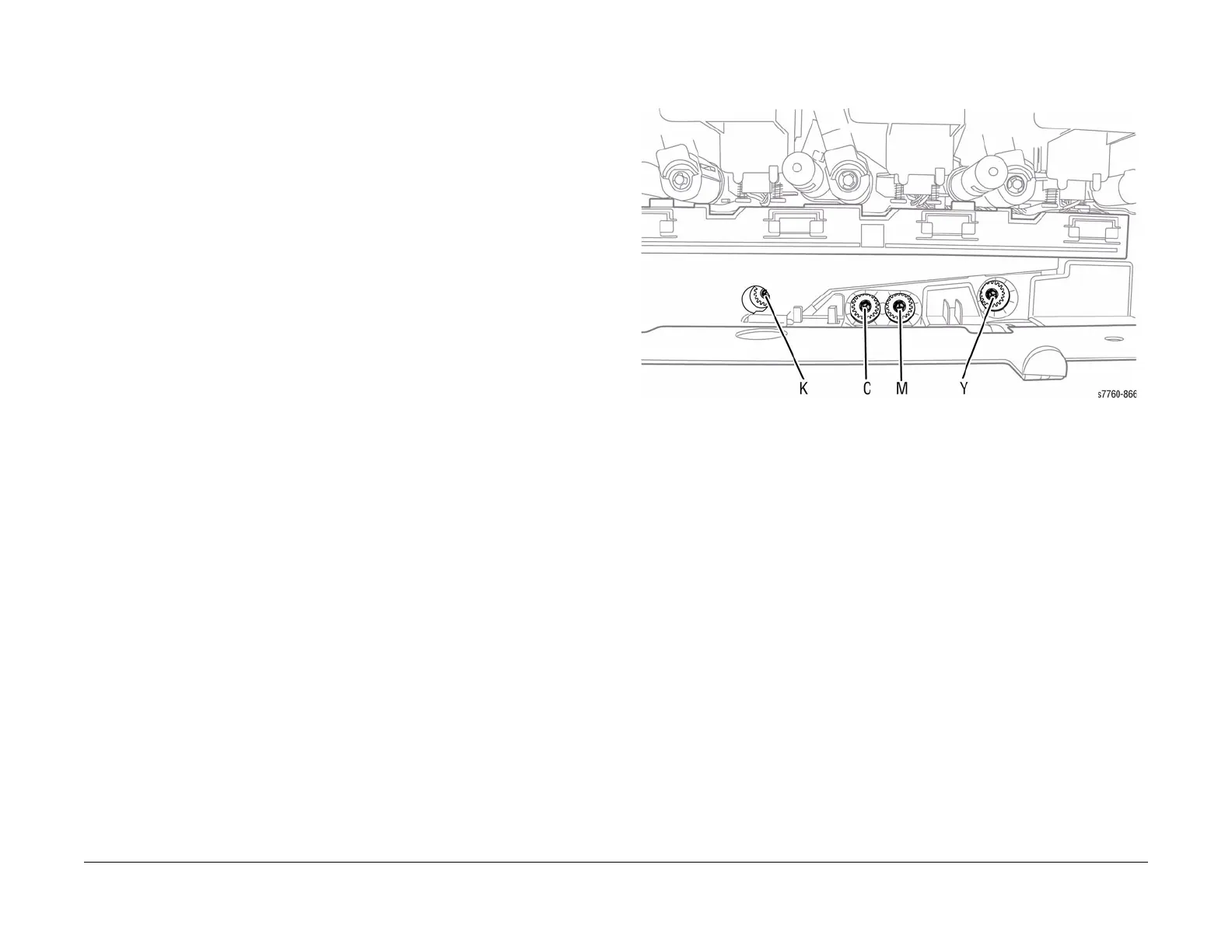
Adjustments should be made only if the skew correction indicated is greater than 5 clicks.
Adjustment screws are located behind the Waste Cartridge, which must be removed for
access. From left to right, the adjustment screws are: K, C, M, and Y.
Figure 1 Adjustment Screws