January 2010
4-16
Phaser 7760 Color Laser Printer
REP 4.4
Revised
Repairs and Adjustments
REP 4.4 Imaging Unit Motor Assembly
Parts List on PL 1.1
Removal
CAUTION
Machine problems will result from careless harness routing during reassembly. Carefully
observe position of wiring harnesses for later reinstallation.
1. Remove the Rear Cover (REP 14.2).
2. Remove the Right Cover (REP 14.3).
3. Remove the Top Cover (REP 14.1).
4. Remove the 24 VDC LVPS Chassis (REP 1.9).
5. Remove the High Voltage Power Supply Chassis (REP 1.6).
6. Loosen the 2 Interface PWB chassis mounting screws and move the chassis up (REP
1.8).
7. Remove the 5 V LVPS Bracket (REP 1.1).
8. Remove the Developer High Voltage Power Supply (REP 1.10).
9. Disconnect the Wiring Harnesses (1 to YM and 1 to CK) to the Print Engine Drive Assem-
bly.
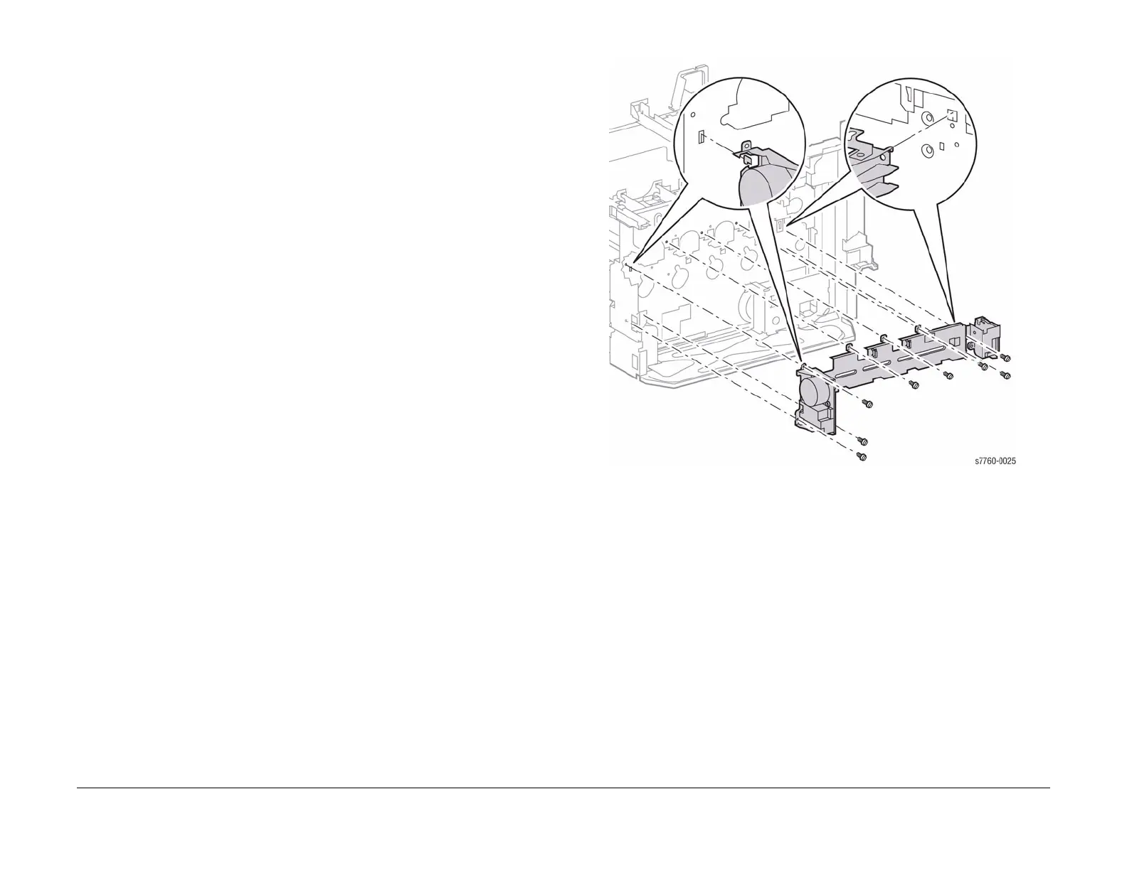
10. Removing the Imaging Unit Motor Assembly (Figure 1).
a. Remove the 2 screws securing the Finisher Connector (now accessible after remov-
ing the Right Cover Assembly) and let it hang loose.
b. Remove 1 screw that is accessible through the frame access hole near the Finisher
Connector.
c. Remove the Wiring Harnesses and Clips from the rear left side.
d. Remove the 8 screws and lift the Imaging Unit Drive Assembly up and out of the
Printer.
Figure 1 Removing Imaging Unit Motor Assembly