January 2010
4-7
Phaser 7760 Color Laser Printer
REP 1.8
Repairs and Adjustments
Revised
REP 1.8 Interface PWB (Engine Control Interface Board)
Parts List on PL 9.1
Removal
1. Remove the Rear Cover (REP 14.2).
2. Remove the Right Cover (REP 14.3).
3. Remove the Top Cover (REP 14.1).
4. Pivot down the HVPS Chassis (REP 1.6).
CAUTION
PWB’s can be damaged by an electrostatic discharge. Observe all ESD procedures to avoid
component damage.
5. Remove the Engine Control Board (PWBA) (REP 1.2).
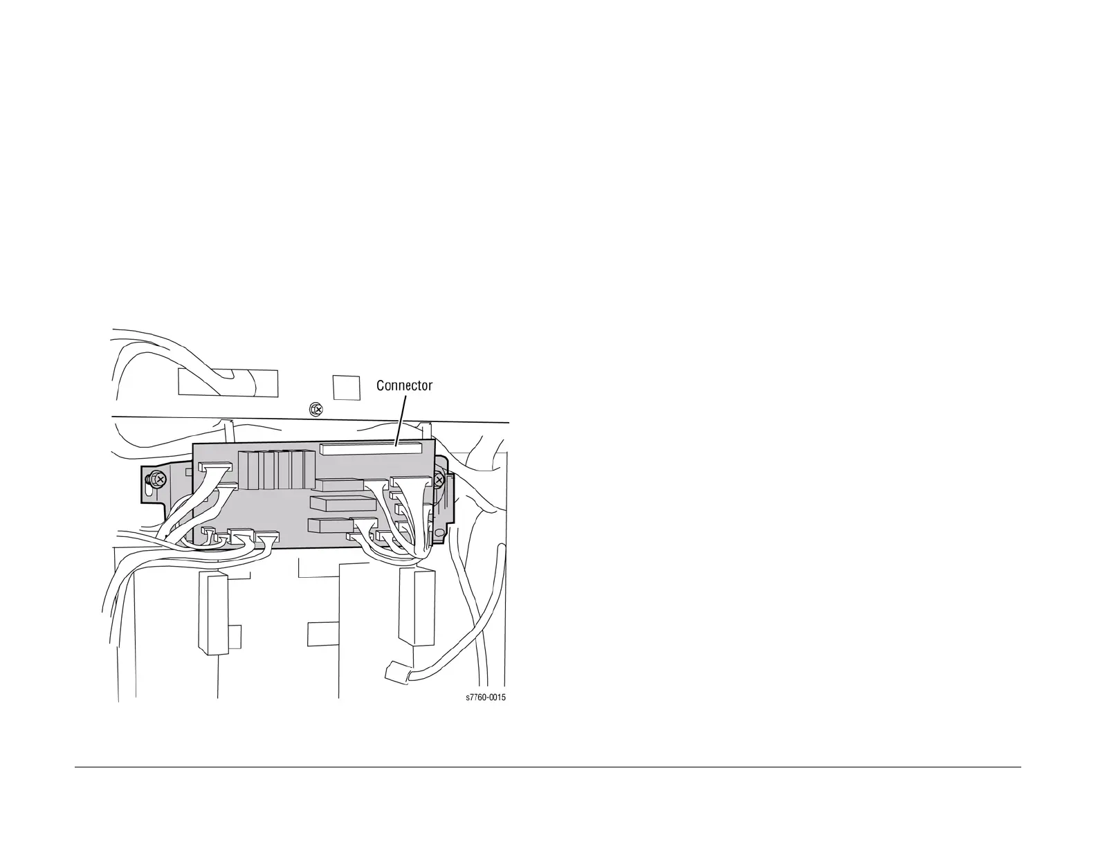
6. Removing the Interface PWB (Figure 1).
a. Disconnect the 15 wiring harnesses (refer to Section 7, Interface Bridge PWB, Main
Motor, LPVS Plug/Jack Locations - Figure 16).
b. Loosen the 2 screws securing the Mounting Bracket.
c. Remove the Engine Control Interface Board from the Chassis.
Figure 1 Removing Interface PWB
Replacement
1. Ensure the 2 screws are positioned in the slots and the Interface Board Connector is fully
seated before tightening the screws (Figure 1).
2. Push up on the Board to fully seat the large Connector with the Engine Control Board.
3. After the Connector is seated, tighten the 2 screws.