January 2010
4-9
Phaser 7760 Color Laser Printer
REP 1.11, REP 1.12
Repairs and Adjustments
Revised
REP 1.11 AC Power Assembly
Parts List on PL 9.2
Removal
1. Remove the Rear Cover (REP 14.2).
2. Remove the 24V LVPS Chassis (REP 1.9).
3. Remove the BTR1 HVPS (REP 1.10).
4. Removing the AC Drive PWB (Figure 1).
a. Disconnect the wiring harnesses on the AC Drive PWB (refer to Section 7,AC Drive
PWB, Noise Filter PWB Plug/Jack Locations - Figure 18).
b. Disconnect the wiring harnesses on the Noise Filter Board (refer to Section 7,AC
Drive PWB, Noise Filter PWB Plug/Jack Locations - Figure 18).
c. Clear the wiring harnesses from their retaining clips.
d. Remove the 7 screws securing the chassis assembly to the printer frame.
e. Remove the complete assembly from the printer frame.
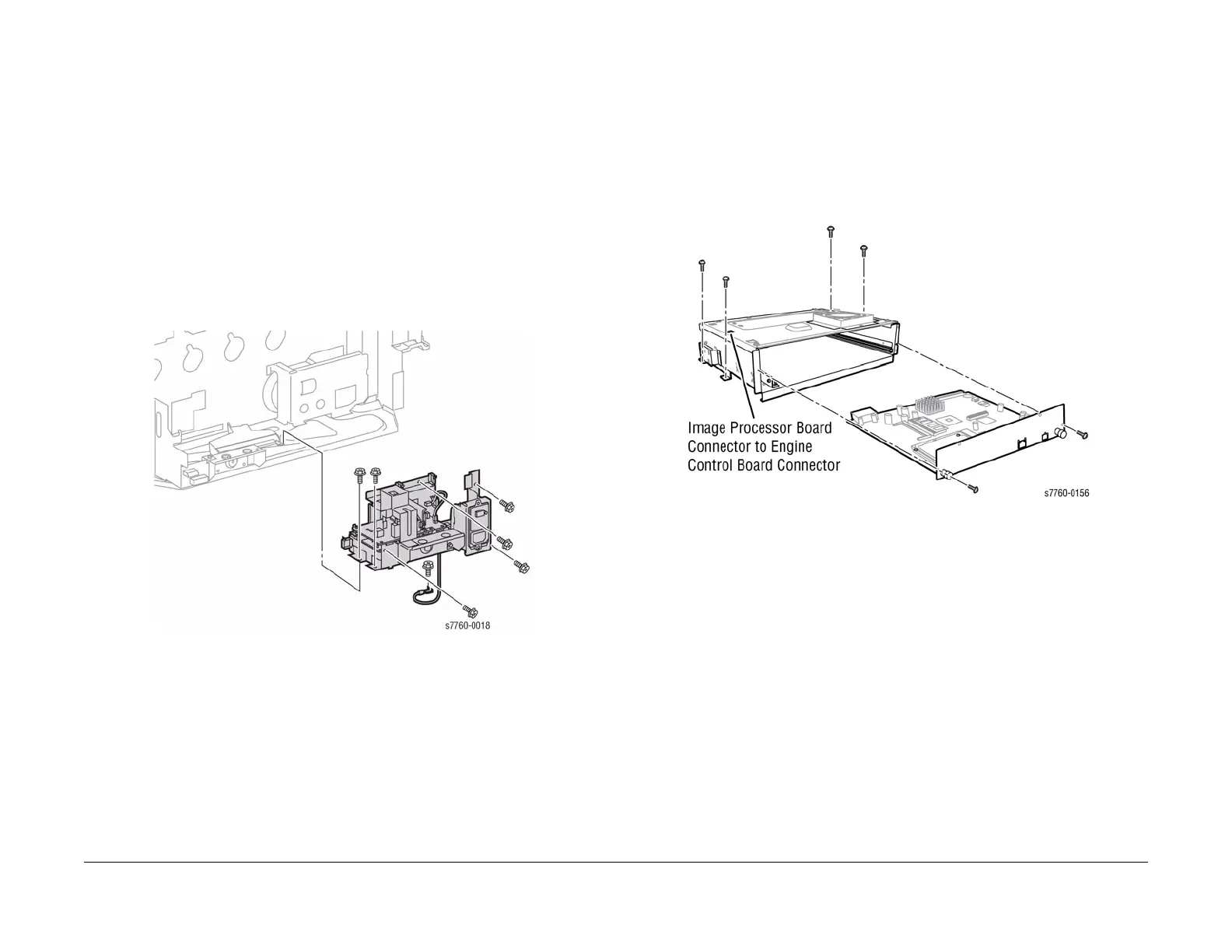
Figure 1 Removing AC Drive PWB
Replacement
CAUTION
Ensure White connector is P43 and Blue connector is P42 (refer to Section 7,AC Drive PWB,
Noise Filter PWB Plug/Jack Locations - Figure 18).
REP 1.12 Image Processor Board (Coordinator PWB)
Parts List on PL 13.1
Removal
CAUTION
PWB’s can be damaged by an electrostatic discharge. Observe all ESD procedures to avoid
component damage.
1. Remove the 2 screws securing the Image Processor Board.
2. Pull the Image Processor Board away from the Chassis to remove.
Figure 1 Removing Image Processor Board
3. Transfer the following parts to the new Image Processor Board.
• Hard Drive
• Memory
• NVRAM
• Configuration Card
Replacement
CAUTION
Ensure the Image Processor Board is fully seated when reinstalling.

 Loading...


